You would have to solder a wire to the positive pin on the motherboard, the negative can come from any header on the MB. These two wires would go to the input to PSU board I linked to in eBay.
You would have to solder wires to the board, it doesn't have sockets on it. There are two input and two out put pins. The output pins would then go the the Cube Sensor board.
YES. The documentation implies the socket on the NUC (the one you don't have) is electrically connected to the external socket, so whenever there is power provided externally you will have power on the internal socket. Note: I am basing this off the DQ77KB MB which is fairly identical.
Of course. If you are not scared off by all of this, then I don't mind provide more details, ie. a wiring diagram. One thing I forgot to mention is the board on eBay has an adjustable output voltage, so you would need a voltmeter to calibrate it to the necessary 5V.
Sorry for delay in getting back to you.
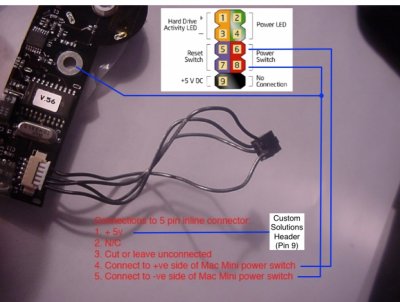
PS I attached the wiring diagram for my Cube Switch - to DQ77KB motherboard. The Front Panel header I think is identical
Kiwi