
- Joined
- May 27, 2012
- Messages
- 759
- Motherboard
- DQ77KB
- CPU
- i7-3770S
- Graphics
- HD4000
- Mac
- Mobile Phone
Powermac G5 (Late 2005) Complete - Design According to Ive
First Powermac G5 (Late 2005) Project - Design According to Ive
This is a project to convert a Powermac G5 (Late 2005) Case for use as modern Intel computer. My main aim in this project is to stay true to original design.
Back in 2005 I purchased the first Mac Mini (G4), and from that time I have been a convert and purchased many Mac machines. Problem was I had to give up interest in tinkering with hardware.
Recently I came across the Tonymac site, and decided to replace a 3-4 year old iMac with a Hackintosh, so built a Sandy bridge based system based on the 2011 recommended build. I didn’t document this build as there were many builds like it. But I caught the bug.
Since then I have spent many hours reading posts on G5 modding, all of which gave me a lot of inspiration. I think building a G5 is a much more of a unique thing I would like to bring some of the best I what I have seen, improve on it while introducing my own ideas. Hopefully in this process I will provide inspiration to other people.
However I would like to say thanks to everyone that has posted before me, I will credit the important posts as I go through each section of the build.
Objectives
The objectives are as follows:
My skills are in electronics (handy with soldering iron) and computer sciences, but little experience with metal working, or painting. I currently only have access, to basic tools including an electric hand drill, but have never owned or used a Dremel. I don’t have access to metal working, or paint shops.
I figure with my skills the less cutting I have to do to the exterior case, the less the case will differ to the original, and the less I will mess it up. I don’t have any dedicated space, so have to use Kitchen / Dining room tables, and makeshift (wobbly) tables in my garage.
This project may take many weeks / months to complete as many of the parts take four weeks to be delivered (from eBay), and since I don’t have a dedicated workspace, so have to pack away after each bit of work, which does slow things down. Also family life with young children
Design
Some of the design elements are:
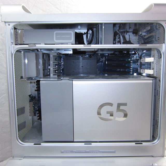
Initial Image of Computer
Not much to say really, this is the inside, compare it to the final images below
Final Image Gallery
I thought I would post the final images so you can see the result of the work.
Here is the outside nothing has changed really. USB/Firewire and Front audio are non-functional.
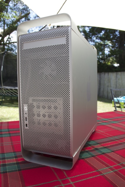
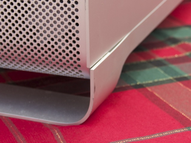
The case has minimal damage, the only serious damage is where the foot got slightly bent. I would fix it if I knew how, but am not worried, it adds character
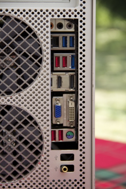
Here is the back, you can see the obvious modification to make the rear IO visible. Note the panel to the left of the fans is original it hides the WIFI antenna, which at this time is not connected.
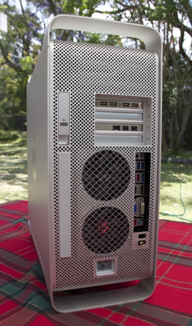
And a closeup. as you can see I have been conservative with the cutting, there are a few ports which are not accessible the main one is the Audio Port. I have installed a short extension cable, you can see it poking out at the bottom.
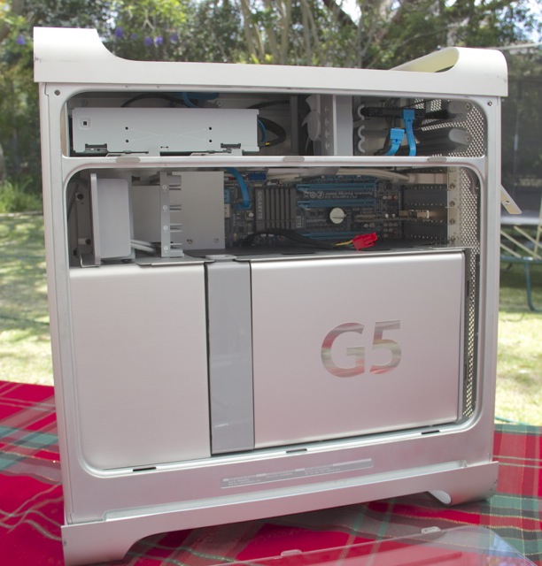
Now the inside of the machine. I have kept it looking as original as possible. The main difference is the cover on the left, which I cut from an old computer case I had lying around, the finish is almost identical. The cover on the right is original as are most of the other components.
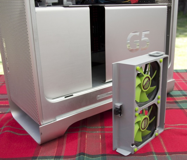
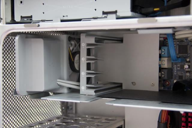
The CPU fan unit can be removed, it was trimmed from the original, and mounted with new fans, but all the mounting and connector is original.
Removing the two covers we get a real look at the inside, where you can plainly see the new 3.5" HDD Drive Bay. The PSU has been installed into the original apple enclosure in the base of the computer

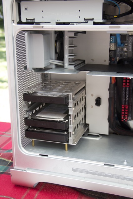
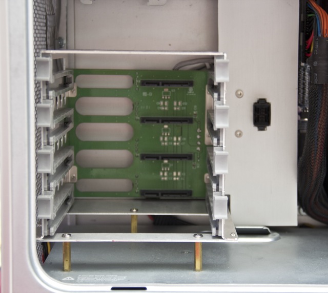
A closeup of the Drive bay. This is a Lian Li drive bay that I converted and installed. This is a tool-less design you screw the rails to the drives then the drives just slide in...
...and mate with the connectors at the back of the chassis. To the right is the Fan connector, and a cover hiding SATA cables that go under the motherboard. This cover also hides a central fan power distribution box.
The motherboard, nothing too much to say, the fans on the right are mounted into the original frame. The divider between CPU and PCI slots has been trimmed for the new motherboard
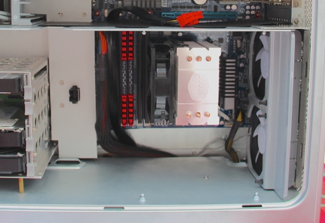
Speaker is connected and beeps on start-up. The cover doesn't hide very much the SATA cables loop back and go straight under the motherboard, so are quite short. The SATA cable on the right is for the optical drive
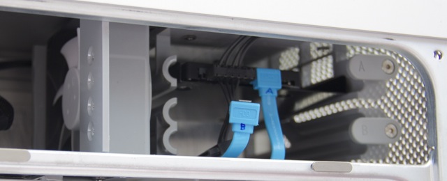
The original optical drives are fully available. I have my boot SSD installed here. In total I can accommodate 6 x 3.5 hard drives.
Hope you like the pictures.
This is the end of he build. There will always be more to-do, but at this time I have a functional computer that meets my needs, in time I may make small changes. Any questions or suggestions let me know...
KiwiSinceBirth
First Powermac G5 (Late 2005) Project - Design According to Ive
This is a project to convert a Powermac G5 (Late 2005) Case for use as modern Intel computer. My main aim in this project is to stay true to original design.
Back in 2005 I purchased the first Mac Mini (G4), and from that time I have been a convert and purchased many Mac machines. Problem was I had to give up interest in tinkering with hardware.
Recently I came across the Tonymac site, and decided to replace a 3-4 year old iMac with a Hackintosh, so built a Sandy bridge based system based on the 2011 recommended build. I didn’t document this build as there were many builds like it. But I caught the bug.
Since then I have spent many hours reading posts on G5 modding, all of which gave me a lot of inspiration. I think building a G5 is a much more of a unique thing I would like to bring some of the best I what I have seen, improve on it while introducing my own ideas. Hopefully in this process I will provide inspiration to other people.
However I would like to say thanks to everyone that has posted before me, I will credit the important posts as I go through each section of the build.
Objectives
The objectives are as follows:
- Keep as much of the exterior look with minimal cutting. While I think installing the MB tray and replacing the backplane is a good solution, I think it does detract from the look of the case.
- Keep the internal presentation of the case similar to before, with simple and uncluttered look. Alot of the look is due to the airflow (fans and panels) so want to keep this as part of the overall design
- Meet the needs of my current mATX & hd3000, but allowing for future upgradability to full ATX SLI if needed. I want this case to outlive the computer that is inside.
- Have fun
")
My skills are in electronics (handy with soldering iron) and computer sciences, but little experience with metal working, or painting. I currently only have access, to basic tools including an electric hand drill, but have never owned or used a Dremel. I don’t have access to metal working, or paint shops.
I figure with my skills the less cutting I have to do to the exterior case, the less the case will differ to the original, and the less I will mess it up. I don’t have any dedicated space, so have to use Kitchen / Dining room tables, and makeshift (wobbly) tables in my garage.
This project may take many weeks / months to complete as many of the parts take four weeks to be delivered (from eBay), and since I don’t have a dedicated workspace, so have to pack away after each bit of work, which does slow things down. Also family life with young children
Design
Some of the design elements are:
- Install an ATX PSU into the apple PSU housing at the bottom of the chassis
- Install mATX motherboard to use existing 4 port PCI mounting bracket
- Build my own custom motherboard tray to accept mATX and ATX motherboards
- Extend (the only exterior cutting) existing IO ports to allow direct access to motherboard IO ports.
- Use a large Passive CPU heatsink and rely on all G5 ducting and air flow for CPU cooling
- Replace all fans with modern silent fans.
- Keep existing internal CPU fan mounting frame.
- Keep existing rear exterior fan ports (depending on IO ports)
- Keep existing Internal Speaker and PCI cooling fan mount
- Keep existing PCI card support frame
- Keep existing Optical drive bay, new SATA drive
- Keep existing HDD cooling fan mounts
- Keep existing 2 HDD drive bay.
- Install additional HDD bay (2 drives not enough)
Initial Image of Computer
Not much to say really, this is the inside, compare it to the final images below
Final Image Gallery
I thought I would post the final images so you can see the result of the work.
Here is the outside nothing has changed really. USB/Firewire and Front audio are non-functional.
The case has minimal damage, the only serious damage is where the foot got slightly bent. I would fix it if I knew how, but am not worried, it adds character
Here is the back, you can see the obvious modification to make the rear IO visible. Note the panel to the left of the fans is original it hides the WIFI antenna, which at this time is not connected.
And a closeup. as you can see I have been conservative with the cutting, there are a few ports which are not accessible the main one is the Audio Port. I have installed a short extension cable, you can see it poking out at the bottom.
Now the inside of the machine. I have kept it looking as original as possible. The main difference is the cover on the left, which I cut from an old computer case I had lying around, the finish is almost identical. The cover on the right is original as are most of the other components.
The CPU fan unit can be removed, it was trimmed from the original, and mounted with new fans, but all the mounting and connector is original.
Removing the two covers we get a real look at the inside, where you can plainly see the new 3.5" HDD Drive Bay. The PSU has been installed into the original apple enclosure in the base of the computer
A closeup of the Drive bay. This is a Lian Li drive bay that I converted and installed. This is a tool-less design you screw the rails to the drives then the drives just slide in...
...and mate with the connectors at the back of the chassis. To the right is the Fan connector, and a cover hiding SATA cables that go under the motherboard. This cover also hides a central fan power distribution box.
The motherboard, nothing too much to say, the fans on the right are mounted into the original frame. The divider between CPU and PCI slots has been trimmed for the new motherboard
Speaker is connected and beeps on start-up. The cover doesn't hide very much the SATA cables loop back and go straight under the motherboard, so are quite short. The SATA cable on the right is for the optical drive
The original optical drives are fully available. I have my boot SSD installed here. In total I can accommodate 6 x 3.5 hard drives.
Hope you like the pictures.
This is the end of he build. There will always be more to-do, but at this time I have a functional computer that meets my needs, in time I may make small changes. Any questions or suggestions let me know...
KiwiSinceBirth


