
- Joined
- Dec 15, 2011
- Messages
- 905
- Mac
- Classic Mac
- Mobile Phone
Well done, Kiwi. Looks very professional! 
Hope, it will work fine.
Good luck
MacTester
Hope, it will work fine.
Good luck
MacTester
What would cause it to die after a few minutes ?Looks excellent so far! Good luck! …be sure to test it for a while to see if it doesn't die after a few minutes as it has been the case with other people before.
Apparently feeding too much voltage to the inverter or something. Neither me or the people that that happened to know what's the issue exactly, but the inverter seems to get fried. There have been success stories, though.What would cause it to die after a few minutes ?
Sorry you fried your inverter. Using MacTesters guidance I measured everything before my teardown, and also my build uses the original PSU, to ensure compatibility.Apparently feeding too much voltage to the inverter or something. Neither me or the people that that happened to know what's the issue exactly, but the inverter seems to get fried. There have been success stories, though.
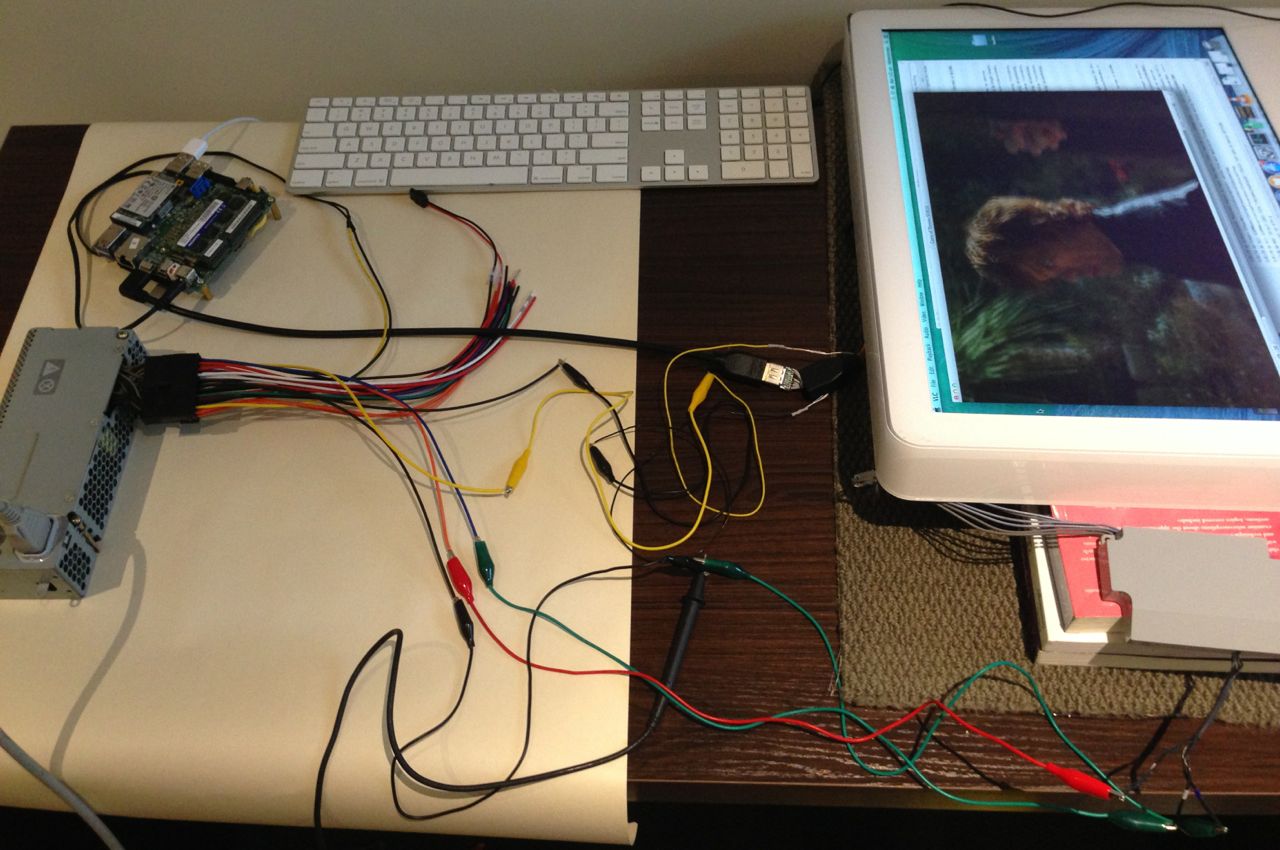
My First Mac LCD conversion went without a hitch, powered on and worked out of the box (so to speak). Playing 720p MKV video produces no artefacts.
Touch Sensors looked straightforward to implement based on what I read. Would be cool if we could keep some sort of common code base, I have some other enhancements planned. Send me what you finish up with, and Ill try and merge it in.Cool!
The HDMI Connector with solder pad is a nice find. I've just ordered one.
BTW:
I was able to get the touch sensors working on the Arduino. Now I try to enhance your code with this functionality. That should allow to adjust the brightness with either the touch sensors or your slider applet...
MacTester
Yes, I will do thatSend me what you finish up with, and Ill try and merge it in.
#include <SimpleTimer.h>
#include <CapacitiveSensorDue.h>

// A general purpose timer, and some misc constants
SimpleTimer timer = SimpleTimer();

//
// CapitiveSenseDue Library
// Paul Badger 2008
// Touch Sensor Pin Assignment & Auto-Calibration
//

CapacitiveSensorDue dnSensor = CapacitiveSensorDue(4,2);	// 1M resistor between pins 4 & 2, pin 2 is sensor pin
CapacitiveSensorDue upSensor = CapacitiveSensorDue(4,6);	// 1M resistor between pins 4 & 6, pin 6 is sensor pin

//Touch Sensor Auto-Calibration
long dnSensorInit1 = dnSensor.read(25);
long dnSensorInit2 = dnSensor.read(30);
long dnSensorInit3 = dnSensor.read(35);
long dnSensorThreshold = (dnSensorInit1 + dnSensorInit2 + dnSensorInit3) + 70;

long upSensorInit1 = upSensor.read(25);
long upSensorInit2 = upSensor.read(30);
long upSensorInit3 = upSensor.read(35);
long upSensorThreshold = (upSensorInit1 + upSensorInit2 + upSensorInit3) + 90;

//
// PIN ASSIGNMENTS---------------------------------------------------------------------------
//

// Inverter Brigtness Pin
const int INVERTER_POUT = 9; // PWM OUTPUT

// PWM Output Pin For Fan
const int FAN_CONTROL_POUT = 10; // PWM OUTPUT Fan Speed Control

//
// GLOBAL VARIABLES---------------------------------------------------------------------------
//

long dnSensorReading;
long upSensorReading;

//
// SETUP (1x during startup)------------------------------------------------------------------
//

void setup()
{
  // setup and init EEPROM, on first invocation.
  setupDevice();

  // Setup Brightness Controller
  setupInverter();

  // Setup Serial command processor
  setupCommand();

  // Setup the BACKGROUND Timers (only needs to be done once)

  // Timer, which triggers the Touch Sensor Control every 200ms
  timer.setInterval(200,touchControl);

  // Timer, which triggers the SerialMonitor every 1000ms (for sensor calibration only!!)
  //timer.setInterval(1000,serialMonitor);
}

//
// MAIN LOOP----------------------------------------------------------------------------------
//

void loop()
{
  // serial ports for command processing
  loopCommand();

  // Let the timer run backgound tasks
  timer.run();
}

//
// DEVICE---------------------------------------------------------------------------------------
//

  //Setup the device if not initialised
  void setupDevice() {

  // Inverter Brigtness
  pinMode(INVERTER_POUT,OUTPUT);
}

//
// TOUCH SENSOR CONTROL------------------------------------------------------------------------
//

void touchControl() {
  long dnSensorReading1 = dnSensor.read(25);
  long dnSensorReading2 = dnSensor.read(30);
  long dnSensorReading3 = dnSensor.read(35);
  dnSensorReading = (dnSensorReading1 + dnSensorReading2 + dnSensorReading3);

  long upSensorReading1 = upSensor.read(25);
  long upSensorReading2 = upSensor.read(30);
  long upSensorReading3 = upSensor.read(35);
  upSensorReading = (upSensorReading1 + upSensorReading2 + upSensorReading3);


  // If the capacitive sensor reads above a certain threshold,
  //  turn on the LED
  if (upSensorReading > upSensorThreshold) {
    Serial.println( increaseBrightness() );
    //digitalWrite(INVERTER_POUT, HIGH);
  }
  if (dnSensorReading > dnSensorThreshold) {
    Serial.println( decreaseBrightness() );
    //digitalWrite(INVERTER_POUT, LOW);
  }
}

//
// SCREEN BRIGHTNESS-------------------------------------------------------------------------
//

int brightness = 0; // current brightness
boolean inverterActive = false;
const int BRIGHTNESS_INC = 10; // todo put this in eeprom

void setupInverter() {
  // get the inital brightness
  brightness = 50;

  // activeate the inverter
  activateInverter();
}

void activateInverter() {
  if (!inverterActive) {
    inverterActive = true;
    setInverterPWMBrightness();
  }
}

void deactivateInverter() {
  if (inverterActive) {
    inverterActive = false;
    setInverterPWMBrightness();
  }
}

// Brightness Write (to the Arduino)
void setBrightness(int bright) {
  brightness = bright;
  setInverterPWMBrightness();
}

// Brightness Read (from the Arduino)
int getBrightness() {
  return brightness;
}

int increaseBrightness() {
  setBrightness(brightness+BRIGHTNESS_INC);
  return getBrightness();
}

int decreaseBrightness() {
  setBrightness(brightness-BRIGHTNESS_INC);
  return getBrightness();
}

// Internally called function (actualize the Inverter PWM Out)
void setInverterPWMBrightness() {
  if (inverterActive) {
    analogWrite(INVERTER_POUT,brightness);
  } else {
    analogWrite(INVERTER_POUT,0);
  }
}

//
// USB SERIAL CONTROL--------------------------------------------------------------------------
//

static const char CR = 13;
static const char LF = 10;

// String input from command prompt
// static String command = String("");

void setupCommand() {

  //Initialize serial:
  Serial.begin(9600);
}

void loopCommand() {

  static char serData[32]; // Buffer
  static int count = 0;

  // if serial port not ready (Leonardo only).
  // dont try to process commands
  if(!Serial) return;

  while(Serial.available() > 0) {

    // read a byte. and add to the buffer
    char inByte = Serial.read();

    // if th read failed
    if (inByte == -1) {
      break;

    // if EOL
    } else if ( inByte == CR || inByte == LF ) {

      // terminate the buffer
      serData[count++]=0;

      //Convert The array to a String
      String command = String(serData);

      // process the command
      processCommand(command);

      // clear the command buffer
      count=0;

    // protect against overrun of buffer
    } else if (count<30) {
      serData[count++]=inByte;
    }
  }
}

/**
 * Brightness increase BI
 * Brightness decrease BD
 * READ Brightness BR -> (000-255)
 * WRITE Brightness BW(000-255)
 */
void processCommand(String cmd) {


  String subCmd = cmd.substring(0,2);
  String extraCmd = cmd.substring(2);

  if (subCmd.equals("BI")) {
    Serial.println( increaseBrightness() );

  } else if (subCmd.equals("BD")) {
    Serial.println( decreaseBrightness() );

  } else if (subCmd.equals("BR")) {
    Serial.println( getBrightness() );

  } else if (subCmd.equals("BW")) {
    setBrightness( extraCmd.toInt() );
  }
}

//
// REFRESH SERIAL MONITOR CONTENT (For Sensor Calibration only)-------------------------------
//

void serialMonitor() {
  Serial.print("\t");			        // tab character for debug window spacing
  Serial.print(dnSensorReading);		// print dnSensor reading
  Serial.print("\t");
  Serial.print(upSensorReading);		// print upSensor reading
  Serial.print("\t");
  Serial.print(dnSensorThreshold);		// print dnSensor threshold
  Serial.print("\t");
  Serial.println(upSensorThreshold);		// print upSensor threshold
}

// END