Contribute
Register

Kiwi's Next Project - iMac G5

Status
Not open for further replies.
Hi Kiwi
Maybe you should just order the boards and replace your handmade one. The only thing you could do at this point is to change the pinout in your software to match mine. Then change your board layout to match. This would make the merging process easier later and we would have more available PWM capable pins for future applications.
Yes I could move the PINS around without much issue, but would like to go a little further, to include your fan control architecture, as this really is one of the bigger advances.

The problem I discovered is finding a suitable P-Channel MOSTFET, in a suitable small package. TO-92 dont seem to provide high enough current. TO-220 is too large and way over kill. The only package I can find is TO-251 which seem to offer a compromise between the two sizes. Your opinion?

Also P channel requires the additional control transistor. N channels seem to be much more prevelant, and easier to control since a controlling transistor can be removed. But I dont think this is an option, because it controls the GND signal of the LOAD. Am I correct ?

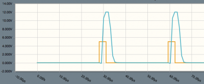
I have simulated this circuit, and I basically works, the only slight issue is the turn off time once the logic level goes to 0, don't know if this is a real issue or could be tweaked with changing component values.
540x405


CircuitLab___Editing__FanControl1_.png

The orange line is the input clock signal, blue is the voltage applied to the Fan.

Can you post some simple code for the fan control logic, and confirm how the hardware for the tachometer works, ie.e what actual signal does this fan pin produce? and how is this converted to RPM.

Thanks as always

Kiwi

Kiwi
 
The problem I discovered is finding a suitable P-Channel MOSTFET, in a suitable small package

Yes, that could be problematic.

Am I correct ?

Yes.

don't know if this is a real issue or could be tweaked with changing component values.

A so-called "totem pole driver" (google for it) will deliver much better turn-off times. A gate resistor is not always needed. It's only intended to improve the EMI behavior (reducing spikes in the square wave). You should start without it and then increase its resistance, until the spikes are gone and you have a perfect square wave on your scope.

Using an N-channel FET on the Hi-side is also possible, but very complex. I did that in my solar MPPT controller: https://www.youtube.com/watch?v=vidzGq0El-U

Can you post some simple code for the fan control logic, and confirm how the hardware for the tachometer works, ie.e what actual signal does this fan pin produce? and how is this converted to RPM.

That's the tachometer schematic (the internal Arduino pullup resistor must be active):
20150109-9142.jpg


Function: The Arduino pullup resistor pulls the analog signal to 5V. If the fan is rotating, the square wave signal from the fan tachometer pulls it down, then it's smoothed by the cap.

This circuit is not able to measure the fan RPM. It's only intended to detect wether the fan is rotating or not. Reason: the Arduino is not able to use interrupts in parallel with all the other tasks.

My current Arduino sketch is in the attachment. I've enhanced your .h file to allow the adjustment of the PWM frequency for all the required PWM pins. The main sketch is almost completely new. EEPROM support is not yet implemented, but the chime, the fans, the temperature sensors, the CCFL brightness controller and the sleep LED are working. The fans are controlled in the fsmFans() function.

MacTester
 

Attachments

  • iMac_G5_SMC.zip
    8.7 KB · Views: 102
hi there,

The pins you refer to on the lcd connector, pins 1,16, and 25 to 30 were specified in the documentation for the LCD panel, but the actual connector to the panel left the pin unconnected. I included them in the documentation for completeness, but you can ignore them if your are converting the original apple cable for hdmi use. Use the third column in the table as your main key to define what needs to be connected.

Hope this helps? And post your results

Kiwi
Ps your English is very good.

Thanks Kiwi, today Im working on the HDMI conversion:

IMG_20150112_161418.jpg

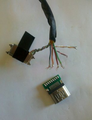
After search and search an adecuate HDMI connector finally I get the correct with the little pcb to solder the cables, and I use a heat shrink tape to ensure a better insulation from the rest of circuit/chassis because on my city nobody sells the connector case.

Here the results:

IMG_20150113_005311.jpg

I opted to use a potentiometer on inverter between 3.3v and GND to control brightness and works OK.

Thanks again!
Pablo.
 
Hi Pablo, great job. Where did you get your hdmi PCB connectors from?

Please post. Thanks!
 
Hi Pablo, great job. Where did you get your hdmi PCB connectors from?

Please post. Thanks!

Hi ersterhernd, thanks! in my country we are having problems with online buys and payment methods with a restriction to u$s money, I can't use Ebay. Fortunately I found this connector in a local electronics store after to visit 5 of them. The price is 45 ARS (about 5 u$s) each one, expensive but high quality. The conversion, assemble and soldering the connector take me 2 hours plus inverter and PSU connections. With the other connector type (SMD or without PCB) is impossible to me to solder on the pins...

ps. Im from Buenos Aires, Argentina.
 
Hi Kiwi
Maybe you should just order the boards and replace your handmade one. The only thing you could do at this point is to change the pinout in your software to match mine. Then change your board layout to match. This would make the merging process easier later and we would have more available PWM capable pins for future applications.
Hi MacTester

This is the approach I would like to take. But will also trying to include as many of your improvements as possible. e.g.

  • I have ordered some of the relays you mentioned, and have included a place for this on the board.
  • Have connected the fan speed inputs, to monitor rotation.
  • GND planes are included, they were originally but I hid them for a better picture.
  • Other minor refinements.

Fan Control

As to FET fan drivers, I have tried the totem pole without much success (at least in simulation). The big issue is these improvements drive up the component count which when multiplied by three drivers, is a bit impractical.

When you move to FET you are basically implementing a switching PSU, which is a much bigger topic, to be efficient you need an inductor, and other things. On our scale just isn't worth the complexity, and realistically only a single controlled output would be feasible in the board size.

Your existing BJT power transistors are at least simple. For the power required by the fans, efficiency of a switching PSU isn't really mandatory.

My solution dissipates (a calculation) a constant ~ 0.6watts for the largest fan, I assume less for smaller fans. So 1 - 2 watts of power can easily dissipated by my miniature heat-sink. I assume your BJT solution power is dissipated, in direct correlation to the PWM duty cycle.

The other advantage of my circuit is the the output of the LM317 is regulated to a specific (variable) voltage with minimal ripple. This can then be read by Arduino as feedback to control the PWM duty cycle, it isn't as good as full Tachometer feedback would be (if it worked).

Have you put a scope or frequency counter on the Fan speed output, what is the frequency range? The Arduino runs at 16MHz, which could be used as a basic frequency counter. I do intend to look at this.

Pinout

I used your pinout except I reversed pins 5 and 6 so that the Fan outputs are all on identical (capability) timers. Timer 4 (the advanced one) is now for backlight inverter.

I want to ty something out with fans then will post revised schema, and PCB

Kiwi

PS I don't have a scope to confirm any of the above.
 
The big issue is these improvements drive up the component count which when multiplied by three drivers, is a bit impractical.

Yes, that's true...

Your existing BJT power transistors are at least simple. For the power required by the fans, efficiency of a switching PSU isn't really mandatory.

They work fine. No heatsink is needed. It doesn't really matter, if you choose a FET or a BJT transistor, as long as you drive it with a square wave (they never run within linear range then).

Especially in the 17" model it's essential to use three independently controlled fans. Why? One of the big fans is located at the bottom. If it runs too fast, then you have no airflow thru the PSU anymore...

Have you put a scope or frequency counter on the fan speed output, what is the frequency range?

No. But I was not able to use the tach signal. The Arduino is just not powerful enough to handle interrupts in parallel with all the other tasks. So I went for my circuit with a smoothing cap.

I used your pinout except I reversed pins 5 and 6 so that the Fan outputs are all on identical (capability) timers. Timer 4 (the advanced one) is now for backlight inverter.

Could be useful. But I was able to enhance your .h file with the required code for changing the Timer 4 PWM frequency.

PS I don't have a scope to confirm any of the above.

I simply used my ears. If you don't hear fan noise, the PWM frequency is > 20kHz. Now I have this cheap Chinese scope: http://www.ebay.com/itm/New-ARM-DSO...pe-/280801651529?ssPageName=ADME:L:OU:CH:3160

MacTester

BTW: my build is almost complete now. Today I've done the first test with the back cover on...
 
I have ordered some of the relays you mentioned, and have included a place for this on the board.

Hi Kiwi

I've ordered some WTV020SD modules yesterday and had this schematic in my head today:
20150120-9199.jpg

Advantages:
- The audio amp is used for the chime too
- Both speakers are used
- The relay is located in the low signal path

Compare with the WTV020SD data sheet page 20: https://docs.google.com/file/d/0B4p82-pNB6o7ck03ZndpYUZGOFU/edit

What do you think?

MacTester
I had thought of this to, my only concern is any additional noise introduced, or picked up by addition of relay will be amplified potentially into audio range. At least with switching on output of the amplifier noise shouldn't be an issue.

I am also concerned with, but haven't resolved, seperate of Gnd planes between audio, and arduino sections of the PCB, don't want all the pwm signals to cross over into the audio circuit

This leads to a bigger problem with my pcb layout, the main AMP and the chime are not in close proximity to one another. If I remove the lm317 regular from my design, then get some more flexibility, but I cannot see an obvious basic layout, that is small and keeps audio seperate

I have order some of the WTV modules, but haven't had any success, reordered some more.

Kiwi

Ps I have ordered a scope, see "eevblog #703", an overkill proberly, but has some great featurs and do much cheaper than last time I looked, I gave never owned anything like this but always wanted one.
 
That's the tachometer schematic (the internal Arduino pullup resistor must be active):
20150109-9142.jpg


Function: The Arduino pullup resistor pulls the analog signal to 5V. If the fan is rotating, the square wave signal from the fan tachometer pulls it down, then it's smoothed by the cap.

This circuit is not able to measure the fan RPM. It's only intended to detect wether the fan is rotating or not. Reason: the Arduino is not able to use interrupts in parallel with all the other tasks.

MacTester
I have been investigating Fan speed detection on an Arduino, and think need to challenge your statement. The basic principle for FAN rpm measuring is documented here http://playground.arduino.cc/Main/ReadingRPM

and it turns out the Leonardo has 5 interrupt pins (2 cannot be used as shared with servo, and PWM pins), so in total three we could use. See here for pin definitions http://arduino.cc/en/Reference/attachInterrupt

In terms of performance I found a blog that states the over head is about 86 clock cycles to invoke and return from an interrupt call. See here https://billgrundmann.wordpress.com/2009/03/02/the-overhead-of-arduino-interrupts/

The interrupt handler only needs to increment a variable, even if long (32 bit) I cannot see how this would take many cycles, but just say 100 cycle (in total) to execute and return from the interrupt.

So:

3000 (average fan rpm) / 60 (seconds in a minute)
x 2 (triggers per fan revolution)
x 3 (fans being measured)

= 300 interrupts per second.
x 100 (clock cycles per interrupt)

= 30,000 clock cycles per second
/ 16,000,000 (CPU Cycles available per second - 16MHz)

= 0.0019 seconds. i.e. 2ms per second that the CPU spends counting fan rotations

This is 0.2 percent of the CPU utilisation to perform this function.

This is very small overhead, but is just the counting, clearly once a second or so you need to derive the rpm, based on elapsed time, but this is trivial.

Have I missed something? Comments ?
 
Status
Not open for further replies.
Back
Top