Contribute
Register

Kiwi's Next Project - iMac G5

Status
Not open for further replies.
Hey Kiwi :headbang:


I have Another Problem i just finished projekt and it works fine:D but now
i have a antoher Imac (IMAC G5 With I sight)and the Pinout 4 the Lcd is Differnt


The lcd is from Samsung ltm201m1-l01 and a data sheet is hier
http://www.datasheet4u.com/datasheet/L/T/M/LTM201M1-L01_Samsung.pdf.html
is a imac from 2006 i think

are you have a pinlayout ?
can you make one with the datasheet


I hope you can help me please i want to have dual screen so much :oops:
 
Hey Kiwi :headbang:
q
I have Another Problem i just finished projekt and it works fine:D but now
i have a antoher Imac (IMAC G5 With I sight)and the Pinout 4 the Lcd is Differnt

The lcd is from Samsung ltm201m1-l01 and a data sheet is hier
http://www.datasheet4u.com/datasheet/L/T/M/LTM201M1-L01_Samsung.pdf.html
is a imac from 2006 i think

are you have a pinlayout ?
can you make one with the datasheet

I hope you can help me please i want to have dual screen so much :oops:
I would ask ersterherd, he has more experience with this specific computer. He has converted the iSight G5 iMac, which may be identical to yours. See This.

http://www.tonymacx86.com/imac-mods/128390-ersterhernds-imac-g5-isight-20-a1145-project.html

However I opened up the PDF you posted and it states LVDS, which is totally different to TMDS for which most of these builds need. So you may be out

Regards
Kiwi
 
thank you Kiwi for that tip :thumbup:

but i dont understand his pinlayout for the display :?:

because he used a lcd cabel from a i mac g4 :crazy: but i dont have somting like this now can i not use the lcd cabel from the imac g5 and directly conect a HDMI or DVI Cabel to it like in your first projekt Kiwi ?
 
Hi Kiwi, I want to make the LCD conversion to HDMI but I dont know where the VSYNC, HSYNC and AGING cables from the original connector are soldered to the HDMI connector pins.

I look at this table: http://images.img5.s3.amazonaws.com/iMac G5 LCD PinoutsV2.png but I don't understand if are non connected or where to make the connections.

Hope you can help me and sorry for my bad english.
hi there,

The pins you refer to on the lcd connector, pins 1,16, and 25 to 30 were specified in the documentation for the LCD panel, but the actual connector to the panel left the pin unconnected. I included them in the documentation for completeness, but you can ignore them if your are converting the original apple cable for hdmi use. Use the third column in the table as your main key to define what needs to be connected.

Hope this helps? And post your results

Kiwi
Ps your English is very good.
 
So my iMc is running really well now. Still some things to finish off, my main annoyance is haven't got the startup Chime to work satisfactorily. But on another sidetrack, I am investigating replacing my SMC with a proper PCB, to that end I have put together a design.

The board is basically the same as before with some slight changes. Mainly a smaller PAM 8403 board, and support for both ISD1820 or WTV020SD-16P (my new untested solution) sound modules

I have found a place in China which will do 10 boards for $30 USD, so not too bad.

What do you think ?

Kiwi

SMCControllerPCB1.png


NOTE: The final diagrams can be found here. http://www.tonymacx86.com/imac-mods/107859-kiwis-next-project-imac-g5-27.html#post985797
 
What do you think ?

Hi Kiwi

Good idea. But I think, that we should try to merge our different hardware platforms. Maybe even could create the "official Tonymac iMac SMC"? Here a short comparison of our approaches:
SMC%20Pinout%20Comparison.png


Advantages:
- The pinout was changed in order to have enough PWM capable ports. (The PWM frequency of pin 3 is not adjustable because of Timer 0, but this is not necessary for driving a LED)
- The fans are independently driven in PWM mode @ 31.5kHz. Less energy is wasted in PWM mode, so no heatsink is needed. The best solution for driving the fans would be a p-channel mosfet.
- Each fan has its own digital DS1820 temperature sensor
- The relay driver in parallel with the chime triggering output allows to use an original speaker for the chime. Sounds much better. (This driver is not yet included in the layout, but the relay was tested last week)
- The fan tach signals are read in order to detect, whether the fans are rotating or not. If not, the PWM value is increased. This allows to drive the fans with very low RPM.
- The Servo output is not in use in this project, but could be useful for drive doors etc.
- I don't have a transistor driver for the sleep LED. The Arduino is able to deliver enough current for the LED.

My current solution (not the newest version). Note that the PCB size should not exceed 95x64mm and the max. allowed component height in the top right corner is about 8mm, in order to fit into the 17" model:
iMac%20G5%20SMC%20Layout.tiff


More things, which would be useful in my opinion:
- Polyfuses for protection of all " low current circuits"
- Poka Yoke capable connectors (not all at the moment)
- Ground plane should cover the entire PCB for better EMI protection

MacTester
 
Last edited:
Hi Kiwi

Good idea. But I think, that we should try to merge our different hardware platforms. Maybe even could create the "official Tonymac iMac SMC"?
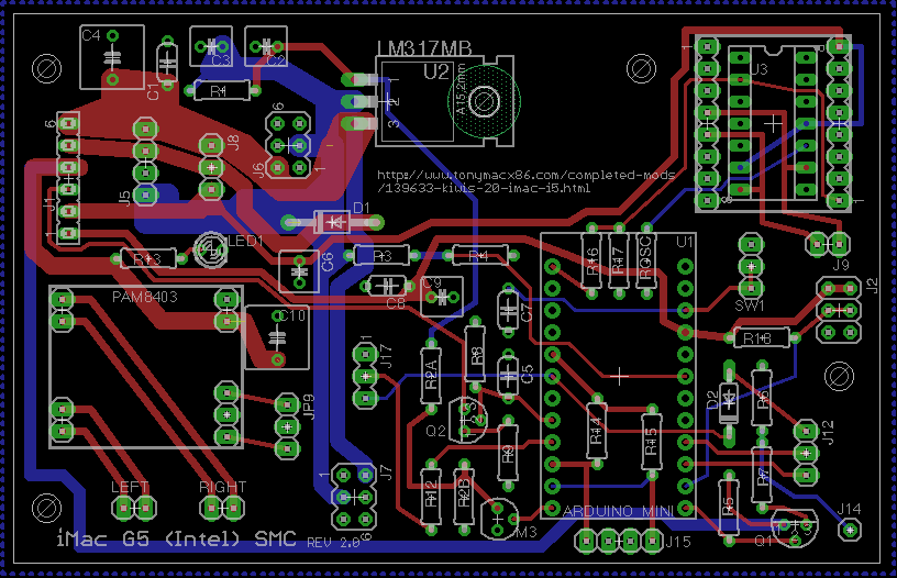
I think its a good idea many of your improvements are things I would have liked to include anyway, but impossible given my late stage of development. The board I produced above, was really designed to be a drop in replacement to my existing board.

Some other things to consider:
  • To be of use is has to be widely applicable, even a cut down version for use in a G4 iMac could be possible, not sure as haven't done a G4 build.
  • Should really be DIY friendly, i.e. using readily available through-hole (no SMD) components.
  • Software should be configurable, so features can be disabled, enabled through configuration.
  • Really need to define goals and features goals upfront including what is mandatory/optional.
Probably next step is start defining some of this stuff, work on an updated schematic incorporating your improvements, Do you have any issue using the Eagle design software?

BUT I don't think this is an overnight job. Also I think it is time for a new thread.

Kiwi.
 
The board I produced above, was really designed to be a drop in replacement to my existing board.

Hi Kiwi
Maybe you should just order the boards and replace your handmade one. The only thing you could do at this point is to change the pinout in your software to match mine. Then change your board layout to match. This would make the merging process easier later and we would have more available PWM capable pins for future applications.

My next step is to complete my iMac project with my handmade board. If it is done, I could have a look at the eagle software and could do some tests with Mosfets for the fan controller.

To be of use is has to be widely applicable, even a cut down version for use in a G4 iMac could be possible, not sure as haven't done a G4 build.
The biggest issue in an iMac G4 is the available thickness (if you want to keep the optical drive). And the fan has a completely different connector. The perfect solution would fit into the "Maintenance Opening" on the back.

Really need to define goals and features goals upfront including what is mandatory/optional.
Maybe we should start a new thread and ask, if there are enough people interested in it. If yes, we could do a survey and ask which features should be realized.

Should really be DIY friendly, i.e. using readily available through-hole (no SMD) components.
Yes, I agree, through-hole technology is better for DIY.

What do you think?
MacTester
 
Status
Not open for further replies.
Back
Top