Contribute
Register

Kiwi's Next Project - iMac G5

Status
Not open for further replies.
Awesome! This is going to turn out beautifully good at the end :D
Thanks, glad you are enjoying it, but as you can see still have a way to go.

The last major hurdle is the Rear IO panel. For USB2 and Ethernet I can just solder to the existing sockets, this should be too hard. But I would also like to replace the Mini VGA with Mini Display Port; and replace the 2 x FW400 with USB3 ports. I have found some suitable extension cables, the plan would be to cut away the existing connectors, and replace and glue/secure the new sockets into position.

This has the opportunity to go horribly wrong. If anyone has any suggestions please let me know.

Kiwi.
 
I did some basic investigation and got it sort of working. It responds to Volume, Play/Pause buttons, but not the brightness buttons. This is on a MBP laptop, I haven't tried on a Hacintosh. It maybe on my laptop that these keys are being trapped, so the event doesn't get through to the Menu.

Kiwi,
Thanks again for your help and for providing your newest releases.

The Arduino sketch doesn't compile:
Code:
iMacG5_Primary6:579: error: 'class FiniteStateMachine' has no member named 'wasInState'
Have you enhanced your FSM library in the meantime?

This has the opportunity to go horribly wrong. If anyone has any suggestions please let me know.
I would recommend to completely remove the old sockets and to replace them like I did it here:
http://www.tonymacx86.com/imac-mods/104625-mactester57s-hemimac-g4-11.html#post658549

Good luck

MacTester
 
The last major hurdle is the Rear IO panel. For USB2 and Ethernet I can just solder to the existing sockets, this should be too hard. But I would also like to replace the Mini VGA with Mini Display Port; and replace the 2 x FW400 with USB3 ports. I have found some suitable extension cables, the plan would be to cut away the existing connectors, and replace and glue/secure the new sockets into position.

This has the opportunity to go horribly wrong. If anyone has any suggestions please let me know.

Kiwi.


Looking at the pic of the rear, Kiwi it looks like the ports mate up at a nice 90 degree angle, unlike the isight version with the horizontal ports. I agree that you solder to the existing ports you can use, and for the extra ones would 90 degree right or left angle usb cables work? I know they are available, and just might squeeze into the space between the logic board and rear white housing. A good dop of JB weld may do the trick to secure them to the logic board.


zei7.png


Ersterhernd
 
Kiwi,
Thanks again for your help and for providing your newest releases.

The Arduino sketch doesn't compile:
Code:
iMacG5_Primary6:579: error: 'class FiniteStateMachine' has no member named 'wasInState'
Have you enhanced your FSM library in the meantime? ...

MacTester
Yes I updated it to resolve issues I was having. See Attached
 

Attachments

  • FSM 2.zip
    45.1 KB · Views: 86
hi ,fantastic work id like to use this method in my I macg4 20 inch inch lcd display ?is that yellow wire going to inverter and the other wire' s destination?also you mentioned that on the 1kohm resistor you soldered ,does 1 end go to pin 18 and the other to pin 19? in order to turn off the backlights?i see that you wrapped one end of the resistor to wire and still left your self with 2 ends of the resistor without adding an additional short piece of wire ? I guess another isn't necessary? thanks im a novice and this is tricky stuffmy hats off to your creative solutions , thganks a bunch :D!
 
hi ,fantastic work id like to use this method in my I macg4 20 inch inch lcd display ?is that yellow wire going to inverter and the other wire' s destination?
Would be great if you could start one of these builds, I can help out as needed. To explain the wiring:

The inverter is powered by 24V and 3.3V, both come from the main PSU, there is a single brightness wire connected to the SMC controller (my) board.

The two additional wires from the LCD cable go to a socket on the SMC board that provide a 12V supply.

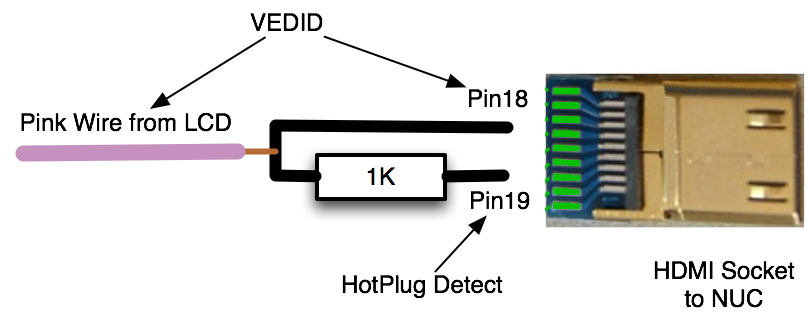
also you mentioned that on the 1kohm resistor you soldered ,does 1 end go to pin 18 and the other to pin 19? in order to turn off the backlights?i see that you wrapped one end of the resistor to wire and still left your self with 2 ends of the resistor without adding an additional short piece of wire ? I guess another isn't necessary? thanks im a novice and this is tricky stuffmy hats off to your creative solutions , thganks a bunch :D!
Yes thats how I did it yes, BTW This part of the circuit control the LCD on/off, not the Inverter On/Off

Update: Not much progress in last week or so, been busy on other stuff.

EDIT: I went back to Post 82 and added a diagram explaining the resistor connection. Copied here

iMac%20G5%20LCD%20HotPlugDetect.png


Kiwi
 
Hi Kiwi

Short question. Did you use a special software for illustrating your PCB layout?

Thanks.

MacTester
 
Project Update

Hi There, been a while since my last post so would give a status update.

Time has been a major issue, other things have taken over in my life. On the good side
I have managed to get the Front Panel LED and Main power button connected and working.
Have stabilised the Arduino code, removing some final bugs.
Small incremental improvements to the brightness Menu software.

Hope to have some time in the coming weeks to work on this.

Kiwi
 
Status
Not open for further replies.
Back
Top