Contribute
Register

An Amazing Find for My Next Project -- iMac G4 20"

Status
Not open for further replies.
have you tested these work? The reason I ask, is these are radio antennas so very susceptible to interference of any kind, proper shielding is exceptionally important.

Kiwi


I will test them when I get my NUC, Kiwi. If the signal works, great, if not I'll have to figure something else out. Even if I don't get pristine signal out of them, its better than nothing and didn't cost me anything.

Time will tell...


Cheers!
 
Build Log 12 -- iMac Microphone Hook-up

The iMac G4 has a small pin-hole microphone at the left bottom corner of the screen. Internally there are three wires that are grouped together with a printed label 'Microphone' on them. The NUC that I will be using has a combination audio/mic jack in it. Its a 4-ring plug rather than 3-ring.

This is the jack that I bought for this build, it supports both audio and mic, but I'm only using the mic function on the NUC, the audio will be handled separately via USB. More on that later.

http://ca.startech.com/Cables/Audio...dset-Splitter-Adapter-Male-to-Female~MUYHSMFF


IMG_4670.JPG


To connect the iMac to the NUC, I used the following diagram from the Intel D54250WYK Product Specification and method for the three MIC wires.


screenshot_124.png


1. Heavy black wire left floating
2. Red wire to RING on the Startech jack (red wire)
3. Light black wire to SLEEVE on the Startech jack (purple wire)
4. Orange and Black wires on Startech jack taped off unused

IMG_4671.JPG


This was the final result. I'll test it when I get the NUC. Hopefully it works. I incorporated a quick-disconnect for convenience.

IMG_4672.JPG


Ersterhernd
 
Looks good, but I would solder as much connections as possible. The spring connections on your breadboards could cause much problems.

have you tested these work? The reason I ask, is these are radio antennas so very susceptible to interference of any kind, proper shielding is exceptionally important.

+1 on that.

Keep it going!

MacTester
 
Hi MacTester, the breadboard idea is scrapped, I soldered everything up yesterday. Rock solid.


Cheers!
 
Build Log 12 -- iMac Microphone Hook-up

The iMac G4 has a small pin-hole microphone at the left bottom corner of the screen.

Snap. I didn't take this into account with my build. I was going to mount a USB audio adapter right where the rear ports are. Now I'm thinking I'll have to get a couple of headphone extenders and run the internal mic of that further up the line.

Thoughts?
 
Hi MacTester, the breadboard idea is scrapped, I soldered everything up yesterday. Rock solid.

:thumbup: :thumbup: Do you have pics?

Snap. I didn't take this into account with my build. I was going to mount a USB audio adapter right where the rear ports are. Now I'm thinking I'll have to get a couple of headphone extenders and run the internal mic of that further up the line.

Thoughts?

The 3,5mm rear ports are not connected in my build. Only the proprietary speaker connector is connected to the internal amp, which is wired to a 50kOhm stereo pot and then to the USB sound device. The internal Mic cable is directly wired to the 3.5mm mic connector on the USB sound adapter. See here: http://www.tonymacx86.com/imac-mods/104625-mactester57s-hemimac-g4-11.html#post659859

MacTester
 
Build Log 13 -- Wired Ethernet

This was tedious. I soldered 8 wires to the ethernet pins on the bottom of the motherboard, then soldered a short piece of ethernet cable to the eight wires. Put a good blob of JB Weld onto the area later so the tiny soldered joints will be protected from breakage. Had to grind away a hair of the aluminum base (on the inside) because the added thickness wouldn't allow the base to seat properly into the I/O. All is good now, and the connection works, I tested it.


Ethernet and Power Switch Wiring

IMG_4674.JPG


Top View

IMG_4673.JPG


Ersterhernd
 
Build Log 14 -- CCFL Dimming of the iMac 20" LCD

This was an important part of the project that I'm happy to report worked out very well. CCFL brightntess control works perfectly with the 20" G4. Using a Picaxe 08M2 microcontroller and two touch sensors, the backlights can be adjusted with easy-to-use touch control.

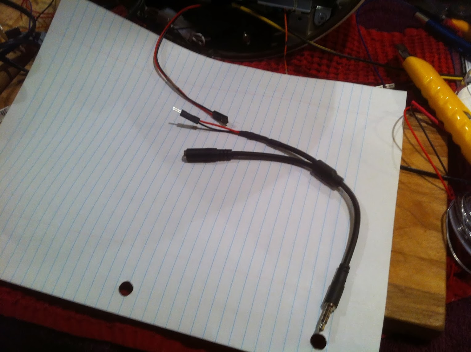
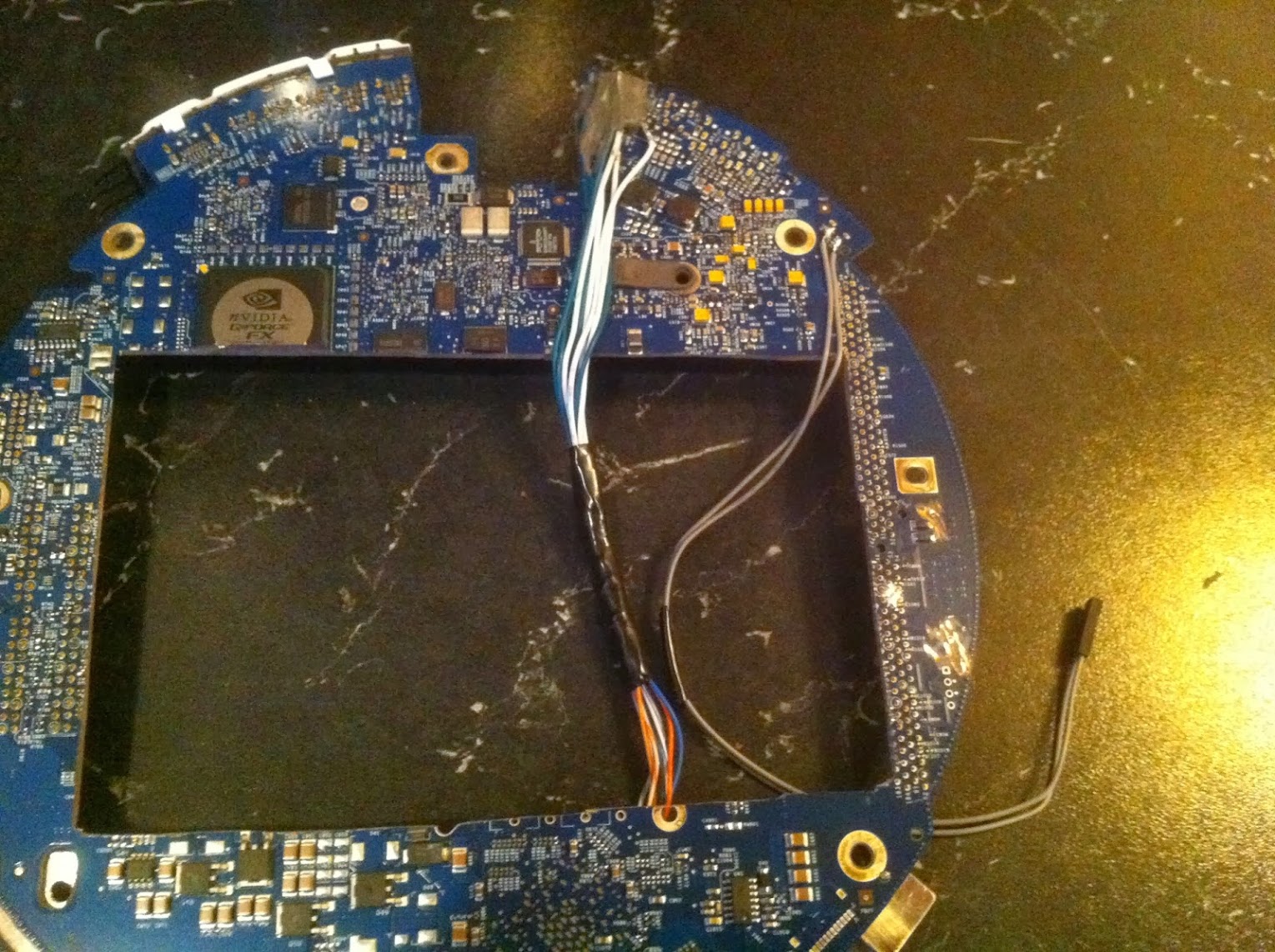
The only wire from the iMac neck that controls the brightness for this application is the YELLOW wire. The purple and orange wires were left floating without any negative effect. In summary, the inverter wiring is as follows --

1. Blue = 24V
2. Red = 24V
3. Black = GND
4. Green = GND
5. Yellow = Brightness Control via 25khz PWM signal (0.63V to 3.2V)


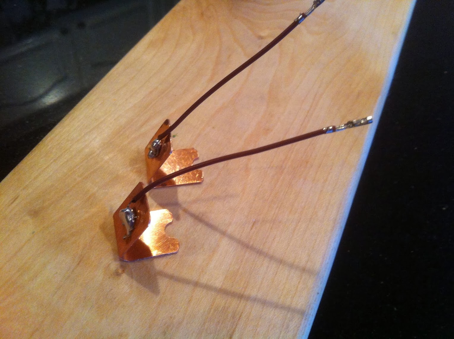
I mounted the touch sensors on the inside of the DVD door, out of sight, yet in an easy-to-find and unmistakable location for brightness control. They are cut from a thin piece of copper plating.

drgx.jpg


IMG_4677.JPG


This is my first-ever attempt at soldering a strip board. With a fresh sharp tip for my cheapie soldering iron, it wasn't difficult at all. Watched a couple of videos first for technique. This board uses a very similar circuit to the brightness control in my 17" iMac G4's. The details are here (different wire colors of course).

IMG_4678.JPG


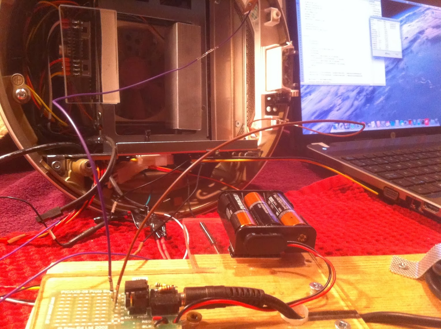
I tested the board first with a small LED on a breadboard. It worked great, the little bulb cycled up and down beautifully. The sensors must be installed in the iMac before the touch capacitance levels can be properly checked and adjusted. I used the Picaxe software to read the levels with the sensors wired from my iMac to my Picaxe programming board.

IMG_4682.JPG


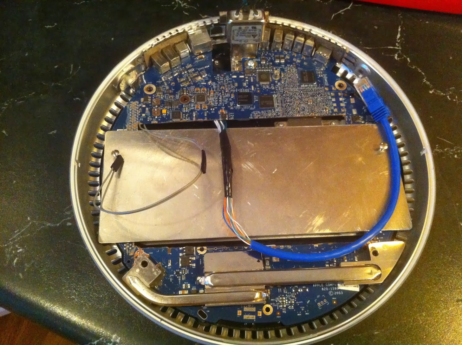
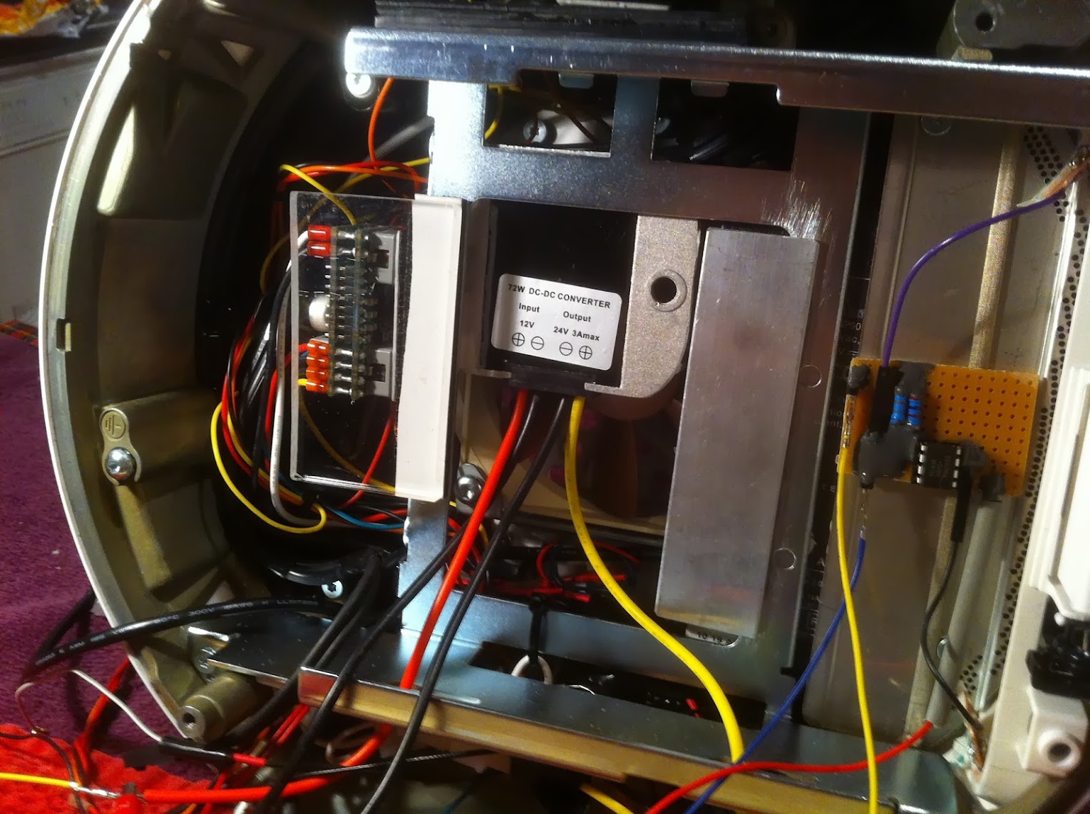
My 24V upconverter arrived just in time to to a real test on the iMac LCD. It just barely fit, I'm glad I ordered the smaller cased version. I also installed my picaxe dimming control board into the iMac. I covered the components with JB Weld rather than electrical tape to prevent shorts from contact with other components; its going to be VERY tight in the dome when this is all done.

IMG_4688.JPG


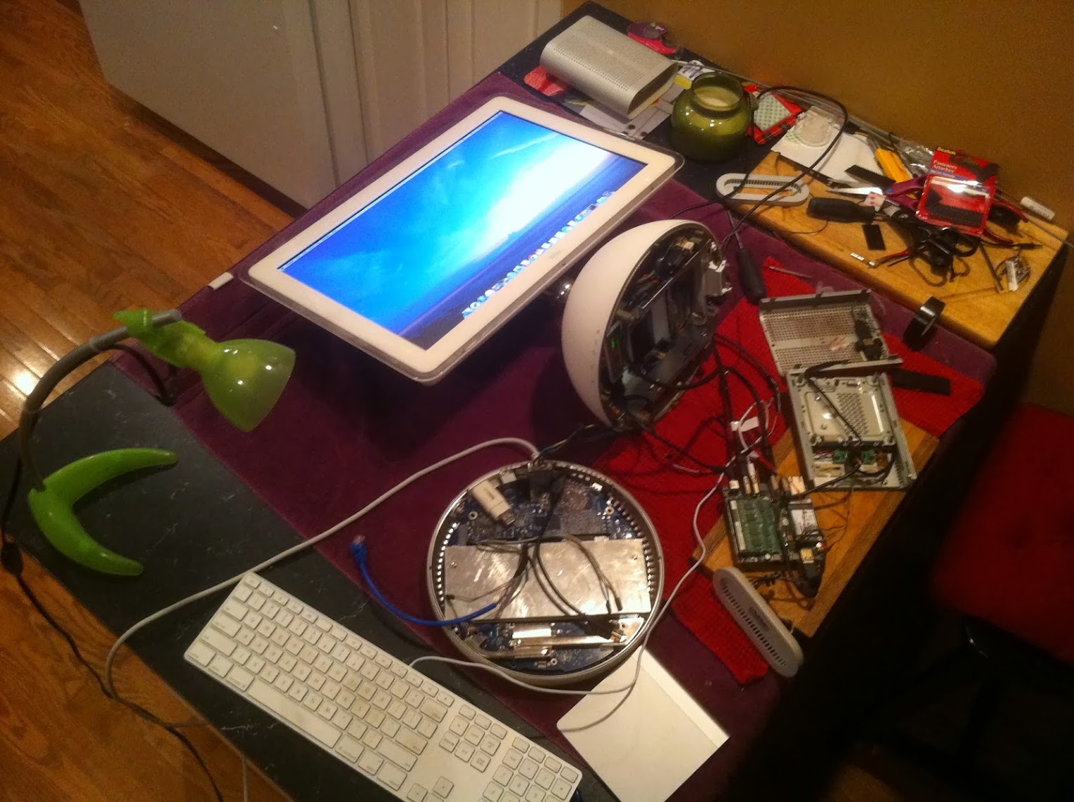
Using a Mavericks install and one of my other Intel NUC computers, I lit the LCD up for the first time with full control of the brightness via the two tiny copper touch sensors. It works great.

IMG_4691.JPG


After the success of this, I ordered my new Intel NUC D54250WYK. I'm confident that this project can be successfully completed now; so I put my money down on one today.


Ersterhernd
 
...

This is my first-ever attempt at soldering a strip board. With a fresh sharp tip for my cheapie soldering iron, it wasn't difficult at all. Watched a couple of videos first for technique. This board uses a very similar circuit to the brightness control in my 17" iMac G4's. The details are here (different wire colors of course).

...

After the success of this, I ordered my new Intel NUC D54250WYK. I'm confident that this project can be successfully completed now; so I put my money down on one today.

Ersterhernd
You are making some good progress. Your strip-board circuit looks great, well done. Good use of JB Weld, amazing what you seem to use that stuff for. I assume the back of the board is also insulated, and you have put some sleeving on the cables that plug into the board.

The NUC is an amazing little product for its size, I have been quite impressed. WonkeyDonkey has pulled together a very good guide, PM him as he is working on a much simplified V2 guide, not sure where he is up to with this.

Kiwi.
 
Hi Kiwi, agreed the new NUC is terrific. Got mine too as my local retailer actually had stock. It took Mavericks like a champ with wonkydonkeys guide.

One surprise that I missed in the tech specs was the 2.0mm pitch headers. I had to order a set. Waiting for those now. This is getting fun now!


Ersterhernd
 
Status
Not open for further replies.
Back
Top