Contribute
Register

[SUCCESS] Gigabyte Designare Z390 (Thunderbolt 3) + i7-9700K + AMD RX 580

I would agree. The LG UltraFine 5K not only has higher pixel density, but also contains:
  • Speakers
  • Microphone
  • Webcam
  • USB hub
  • Ability to charge connected laptop computer at the same time, all over a single cable
These are incredibly useful features. A built-in webcam in today's work-from-home environment is part of the reason these monitors were sold out for quite a while.

The integration with macOS was a big sell on me getting mine. I wanted the native sound and brightness controls without workarounds, and it was a high quality display.

I also now have a built in webcam that is better than my 2012 iMac. I tried a Logitech BRIO 4K before but it seemed to work badly on macOS, both real and Hackintosh.

I wire my Magic Keyboard 2 in back, can charge my Magic Mouse 2, and still have a port for my iPhone. Also, it matches the look of the rest of my components well.

What's also nice is I can use the disable USB wake methods from your guide but keep my keyboard plugged into the monitor and one key wake still works, so if I had one of those CPU coolers that cause sleep/wake issues due to USB, I can fix it that way without losing one key wake.


Wow, I had no clue about this. I mean, you get what you pay for I guess. It is a plus to have it all in one.
 
Not sure I understand the question. Also please note that when there are two or more Thunderbolt controllers in the system, then each one should be given a different Bus ID. The easiest way to do this is by using HackinDROM.

Create one SSDT for each Thunderbolt controller. Use the Customize and Compile icon to set RP21, change Bus ID, and assign unique ID. Then download the .aml file using one of the "disk" icons (see 2nd screenshot).

Please experiment with HackinDROM and let us know if you still need assistance.

@CaseySJ, thank you...It works.... you are a genius..
 
@CaseySJ i'm sorry for the offtopic. I have a Gigabyte Z390 Aorus Master with an i9900K, everything is working excellent, except sleep.
The problem is my WiFi/BT card (DW1560). If i disconnect the card, my hack goes to sleep.
Usbport.kext is for sure ok. I have try pci-e x1 and 3, also i have try different combination of usbport.kext
Do you have any thoughts?
Please see Sleep Aid:
 
I found this perfect workaround for anyone with a Promise Pegasys raid that is no longer able to mount after installing Big Sur

 
@CaseySJ or anyone else knowing about this.

We're following this guide:** Mini-Guide for Flashing SPI ROM Chips using 3.3V CH341A Programmer ** from 11th August 2020.

We're confused about the part where we connect from the CH341a to the ribbon cable of the clip. The ribbon cable got 10 pin connector, which is confusing.

IMG_1120.png


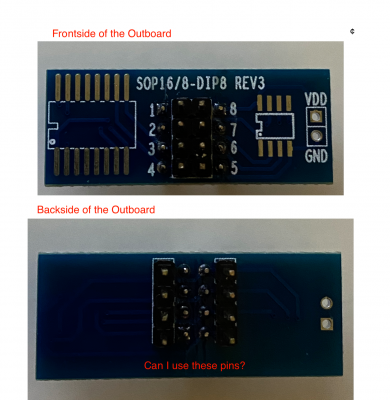
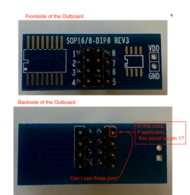
The other part is, do we need the outboard, or can we just connect M/F jumpers from the CH341a SPI connector pins to the ribbon cable without the outboard? And if we need the outboard, can we connect the ribbon cable connector to the outboard, and use the pins on the outboard from the backside, connecting the jumpers to it from the CH341a?

Screenshot 2020-10-01 at 15.40.47.png


Another thing is, we're confused about CH341a how to plug in the jumpers, where there has been mentioned in the diagram/picture "pull out both jumpers and connect them to pin 2 and 3".

IMG_1117.png


We have labeled each pin with numbers on the picture above. If you could please refer to each one, if that would help telling which one to connect.

Any help would be greatly appreciated. :)
 

Attachments

  • Screenshot 2020-10-01 at 15.40.47.png
    Screenshot 2020-10-01 at 15.40.47.png
    1.9 MB · Views: 46
  • Screenshot 2020-10-01 at 15.40.47.png
    Screenshot 2020-10-01 at 15.40.47.png
    1.9 MB · Views: 42
@MuffinCrumbs,

The guide contains a link to an SOIC8 clip. The term SOIC8 means that the clip has only 8 pins and its ribbon cable also has only 8 wires. Please check if you ordered this item:
https://www.amazon.com/dp/B07BRSVRXV/?tag=tonymacx86com-20

Regarding the jumpers on the Arcelli CH341a, each jumper has three pins: Pin 1, Pin 2, Pin 3. There is no pin 4 or 5 or 6 because each jumper is independent. So both jumpers have a Pin 1. Both jumpers have a Pin 2. Both jumpers have a Pin 3.

We attach the clips to Pin 2 and Pin 3 on each jumper.

I have revised the diagram in the original guide to make this clear.
 
Last edited:
@MuffinCrumbs,

The guide contains a link to an SOIC8 clip. The term SOIC8 means that the clip has only 8 pins and its ribbon cable also has only 8 wires. Please check if you ordered this item:
https://www.amazon.com/dp/B07BRSVRXV/?tag=tonymacx86com-20

Regarding the jumpers on the Arcelli CH341a, each jumper has three pins: Pin 1, Pin 2, Pin 3. There is no pin 4 or 5 or 6 because each jumper is independent. So both jumpers have a Pin 1. Both jumpers have a Pin 2. Both jumpers have a Pin 3.

We attach the clips to Pin 2 and Pin 3 on each jumper.

I have revised the diagram in the original guide to make this clear.


Thank you for your reply.

Yes, that is the clip that was ordered.
IMG_1123 2.png


As you can probably can see, the clip is SOIC8 with 8 pins. The ribbon connector is with 8 wires connected to the clip. But the ribbon connector end got 10 pin connectors. Is this wrong?

IMG_1127.png


I think we got the Jumper pins part correct. Thank you so much for that.

Sorry for all this, just so confusing. I got someone who's helping me with this. But none of us have done this before. :)


Edit:
Also a bit confused about the outboard, is it necessary to use that, and if so does the ribbon connector connect to it, and then we use the pins on the back of it?
 
Last edited:
...
As you can probably can see, the clip is SOIC8 with 8 pins. The ribbon connector is with 8 wires connected to the clip. But the ribbon connector end got 10 pin connectors. Is this wrong?
The ribbon connector I received has 8 pins on the black connector at the opposite end from the clip itself. Hence, it has 8 wires and a black connector with 8 pins. If yours has 10 pins, then the extra two can be ignored. I believe you've already identified the correct 8 pins.
...
Edit:
Also a bit confused about the outboard, is it necessary to use that, and if so does the ribbon connector connect to it, and then we use the pins on the back of it?
The extra board (i.e. the "outboard") is optional. If it helps it can be used. It's included in the package just in case someone needs it.
 
Back
Top