Contribute
Register

Upgrading my G3 to G5 mod WorkLog

Status
Not open for further replies.
looking good.
interesting way to mount the psu. i too have alot of m3 screws and things laying around. used to dabble with nitro rc, so still have some spares kicking about.

have you thought about how you are going to reattach the rivets on the side?
 
samisnake said:
looking good.
interesting way to mount the psu. i too have alot of m3 screws and things laying around. used to dabble with nitro rc, so still have some spares kicking about.

have you thought about how you are going to reattach the rivets on the side?

Lots of m3 nuts/bolts! most of the rivets I drilled out aren't very necessary, seeing that there's also about a million screws holding the case together
 
so how are you going to attach the m3s though?
 
So my Mountain Mods Tray came in, and I realized I made one little mistake when ordering...

3013.jpg


And this thing took so long to to get here, I swear, FedEx must've hired someone to walk it across the country to my house. There is no way I am returning this... and in comes in what I call "The Adjusters."

3014.jpg


So I drew everything out using calipers, squares, and rulers to make everything look nice...

3015.jpg


...and used a tablesaw and jigsaw to cut it out

3016.jpg


Here's how it will look!

3017.jpg


Since I didn't have any more dremel cutting wheels, I cut out the expansion card slot with an angle grinder. Surprisingly I didn't cut up my chassis.

3018.jpg


3019.jpg


3020.jpg


I then added half a dozen standoffs to the motherboard tray, so that when I attach it to the chassis, I have some clearance to run my wiring underneath the motherboard.
3021.jpg


3022.jpg


The next 3 pics are with my mobo in the tray, ready for fitting. The second graphics card is just a placeholder that I put in to help hold the tray sturdy. Funny anecdote about the radeon 5870- In my previous case, there were no slots for the "tongues" of the pci card, so I had bent them at a 90 degree angle so the card would fit in and attach to the motherboard. I had to flatten that back out in order to work in a proper case. I guess this is the only time anybody has fixed their $400 graphics card by smashing it with a hammer :thumbup:

3023.jpg


3024.jpg


3025.jpg


And here is the final placement! It is held against the back with just 1 screw and is sitting against the chassis at the moment

3027.jpg


And here it is from a bird's eye perspective. I thought it was fitting because when taking this picture a bird flew into the garage and scared the crap out of me, hit the wall, fell and hit the floor, then got up and flew away.

3028.jpg


And last but not least, here it is with the outer plate on.

3030.jpg


As you can see, I still need to cut out the I/O / PCI hole, and I need to patch up the stock fan holes. For now I am leaving those stock fan holes, but I want to buy just the front grille of another power mac, so I can cut a piece out , JB weld it in, and make it look like there was never any hole there. Obviously, if anybody has any spare G5 grilles, please PM me!

Until then, I plan on using a bit of crazy glue to hold the standoffs in place where I want them, then removing the motherboard tray so that I can JB weld them real good without anything in the way.
 
While waiting for my JB weld to dry, I decided to paint the motherboard tray and I/O shield metallic blue, since everything inside the case will be a nice electric blue color!

3031.jpg


2 Days after the JB weld was put on, I decided to continue working on the I/O panel, so I used the jigsaw and cut out the inside so my ports would be usable! To do so I had to nearly bolt the entire case back together in order to hold everything down in place. Even with everything held down as much as possible, the saw would start to grab and shake everything to bits. it shook so much that the latch, which looks to be spot welded to the chassis, shook right off! In the end, it is looking pretty nice, although I need to go back and take a little more off the one corner. After that, I drilled out where my screws go, so that I could bolt the tray pieces together through the mesh, and make everything alot nicer and alot sturdier. now all that's left is to take care of that hole!

3036.jpg


And Here it is with everything so far bolted in place!

3037.jpg


I've recently contacted Swiftech about my water cooling stuff, but unfortunately they still have no word on when they will be getting the GPU block I ordered... I kinda need that, along with the rest of my order, pretty soon, as I need to make room for a 240mm x 120mm radiator in this case!
 
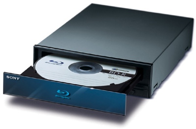
So I got a new piece of hardware for my Power Hack, and since I had some time to work on it, I get to bring you another update! I picked up a used Sony BWU-200S Blu-Ray Burner!

Sony-BWU-200S-Blu-ray-burner.jpg


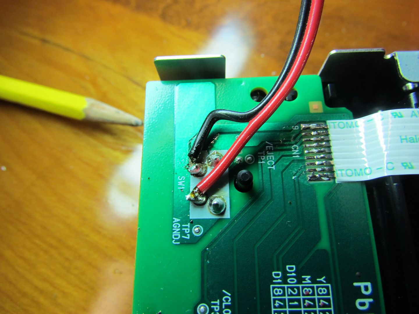
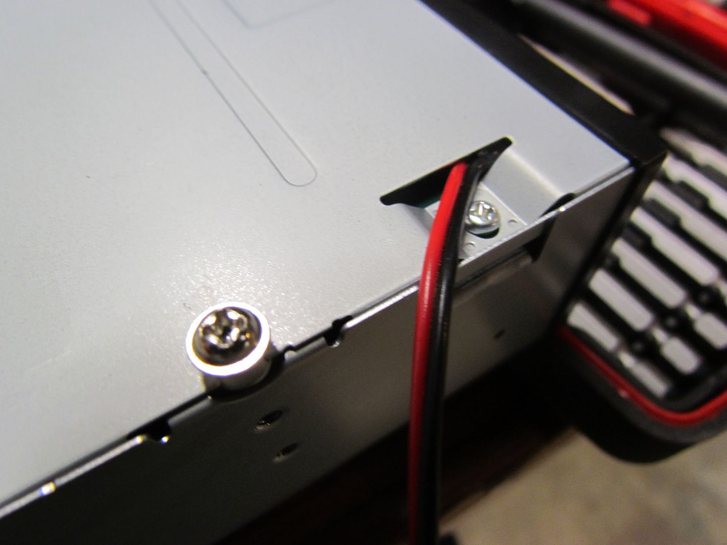
So what was the first thing I did with my new expensive drive? That's Right! I voided the warranty! I ripped it open and soldered a pair of leads that now are just dangling outside the drive. soon I'll cut and trim it and do some sort of hidden dvd drive button.

IMG_3038.jpg


IMG_3039.jpg


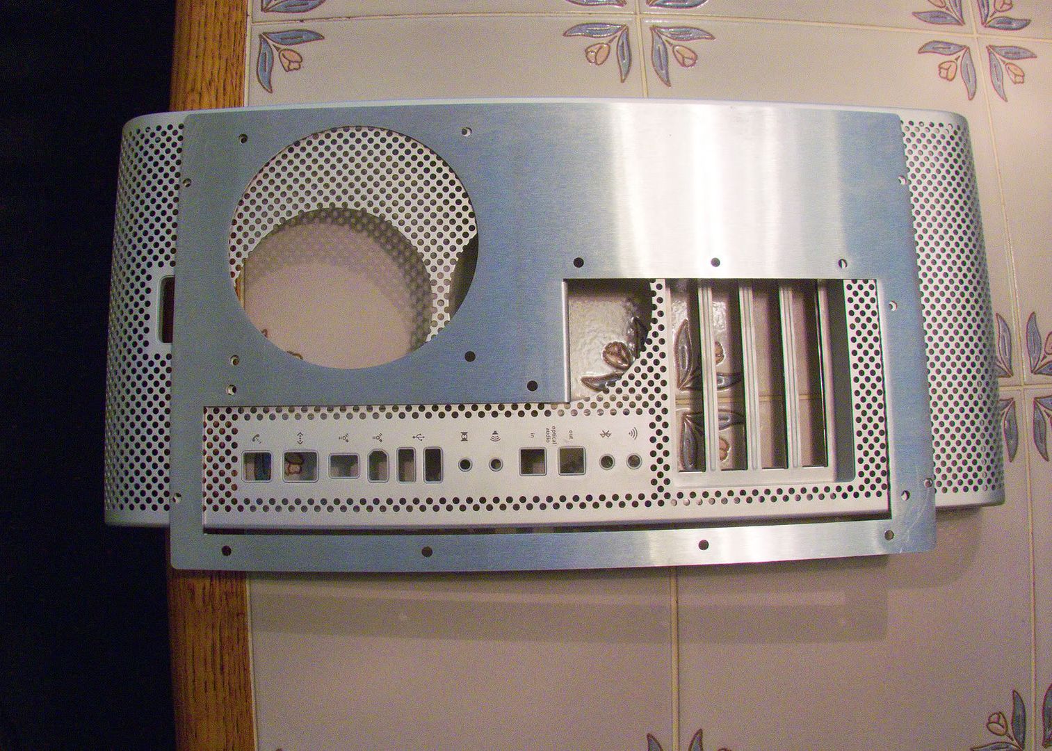
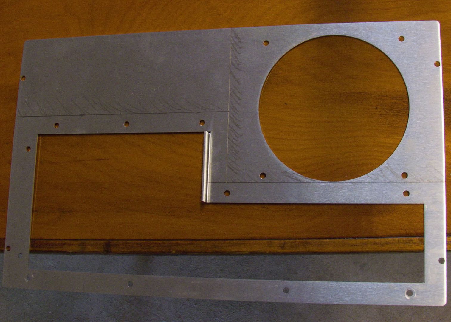
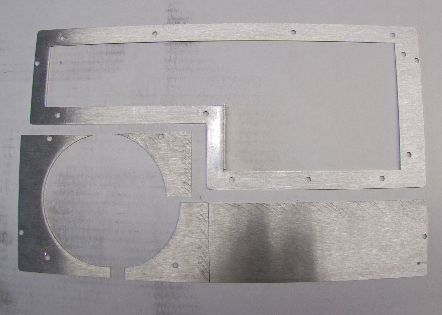
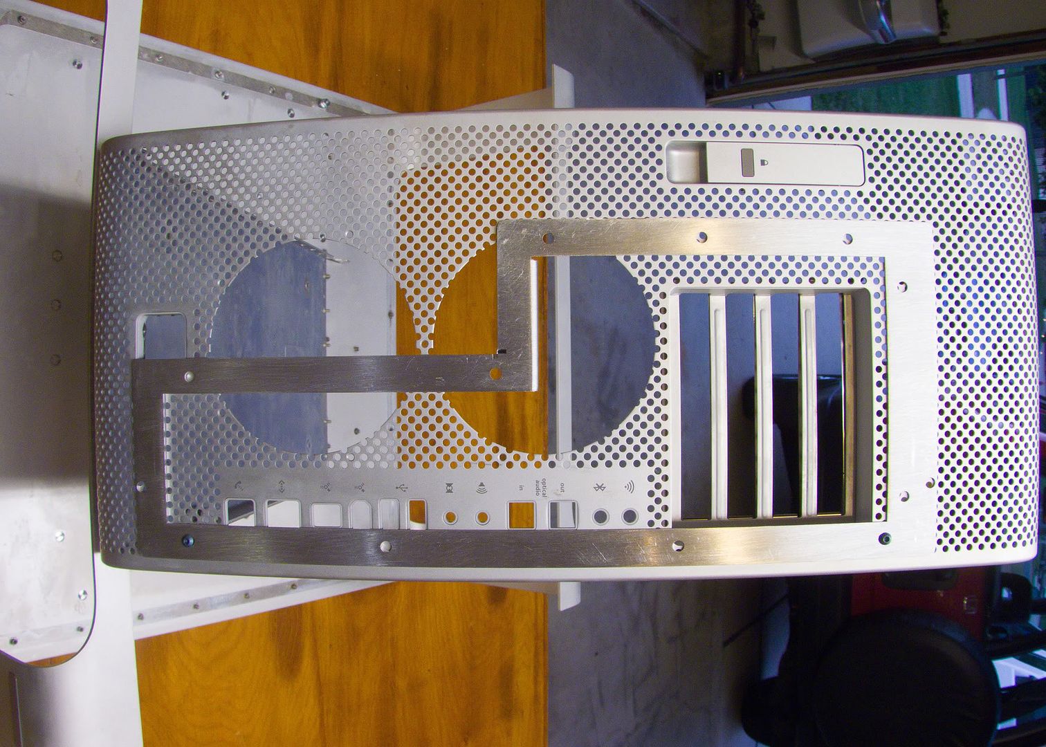
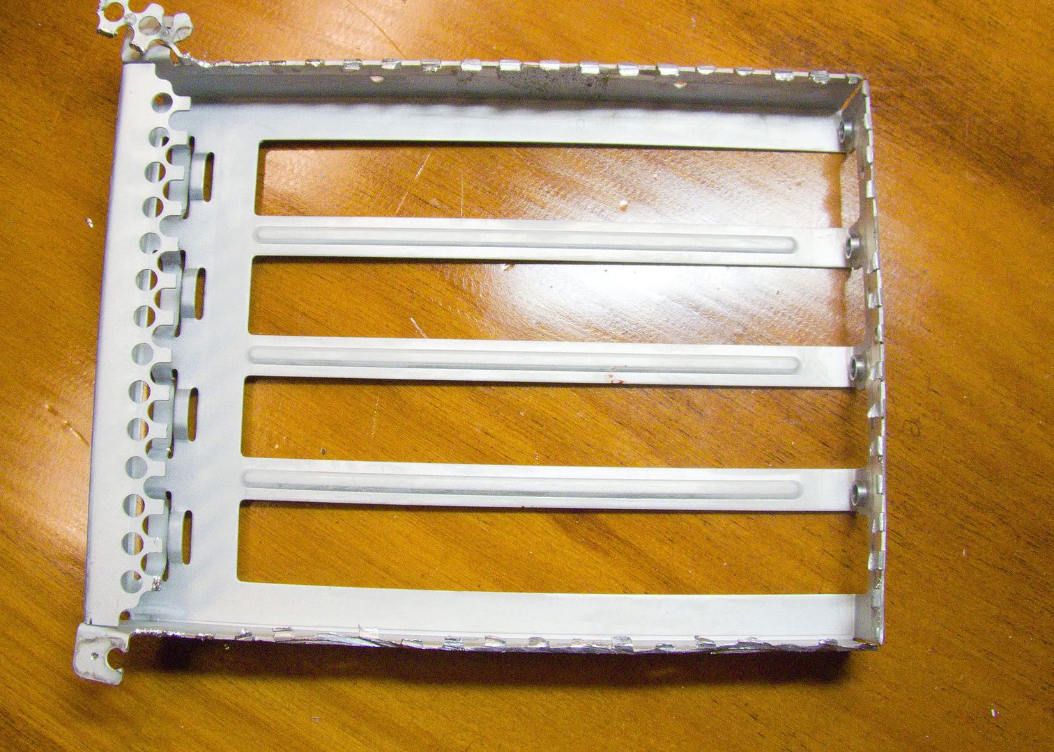
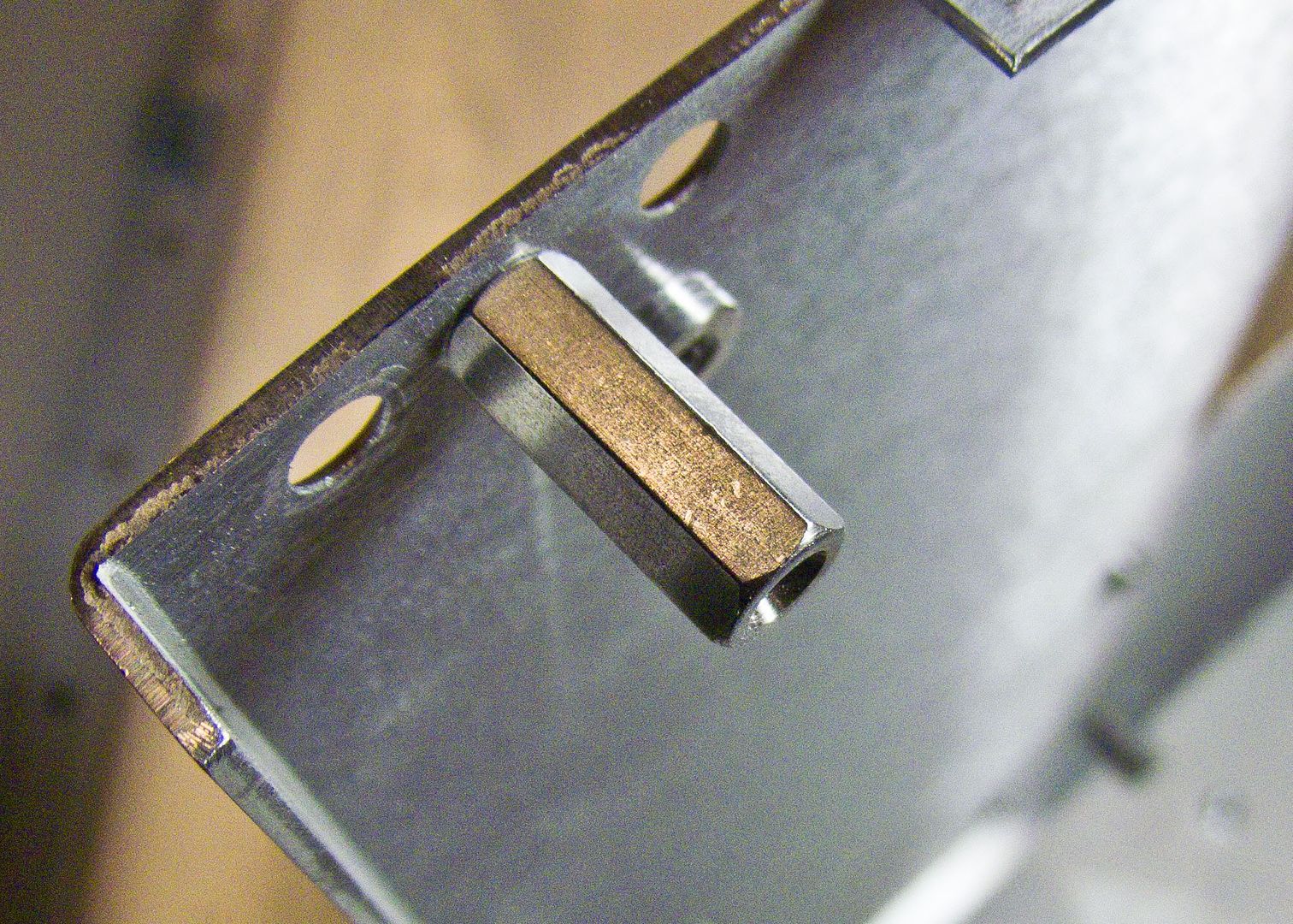
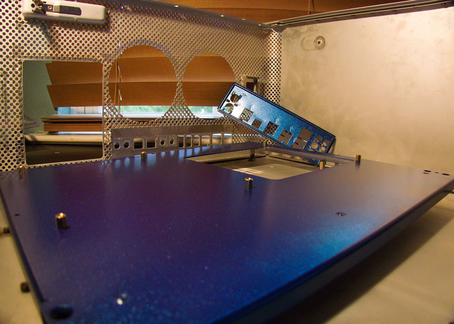
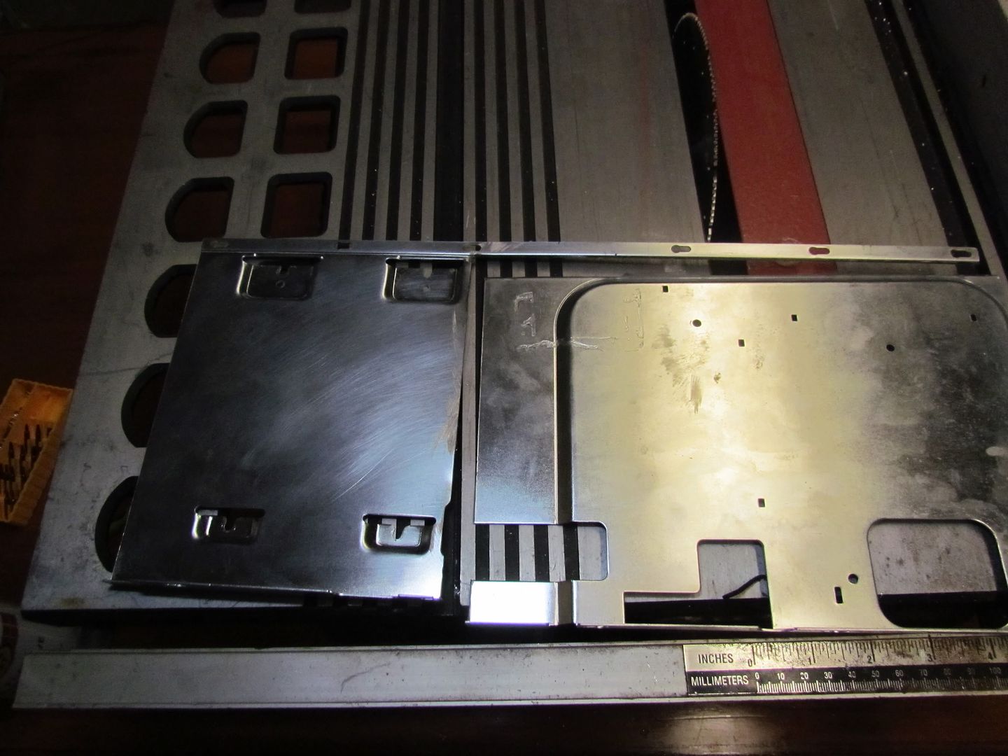
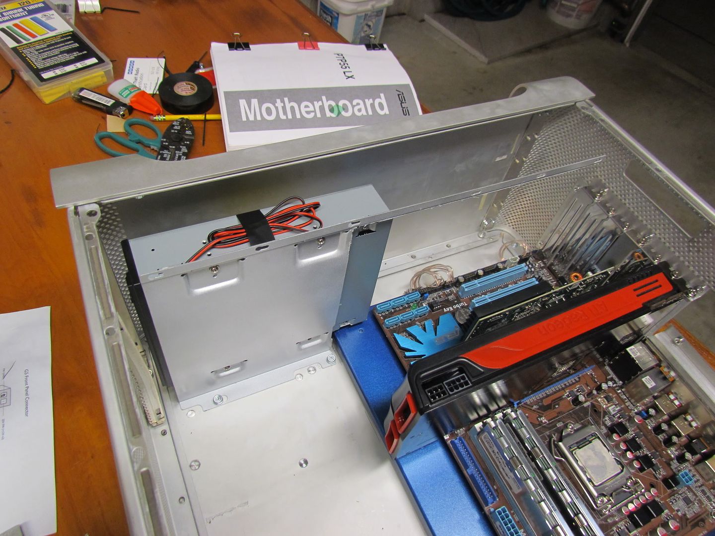
After wiring that up, I worked on the plate that holds the drive in place. I had to do some cutting so that I can still keep the latching system, but had room for the motherboard. I ended up with this:

IMG_3042.jpg


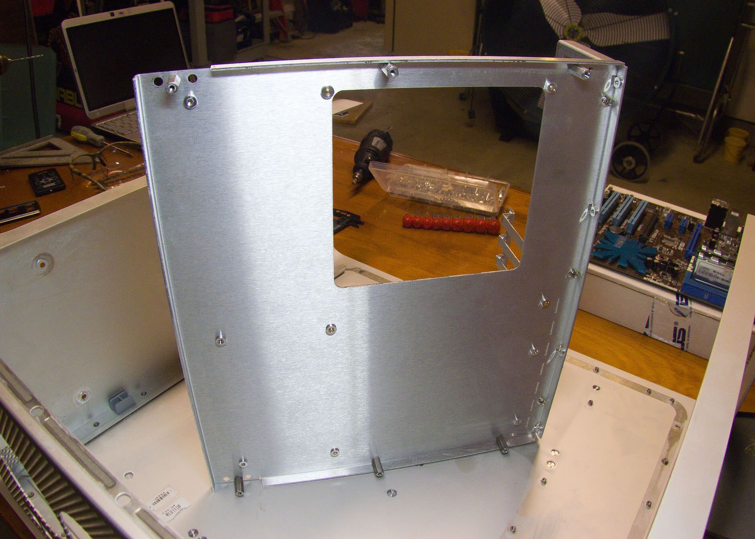
I then put a coat of flat white paint, followed by premium wheel paint, which looks pretty close to the mac's brushed metal look. I may end up doing the entire case in this stuff!

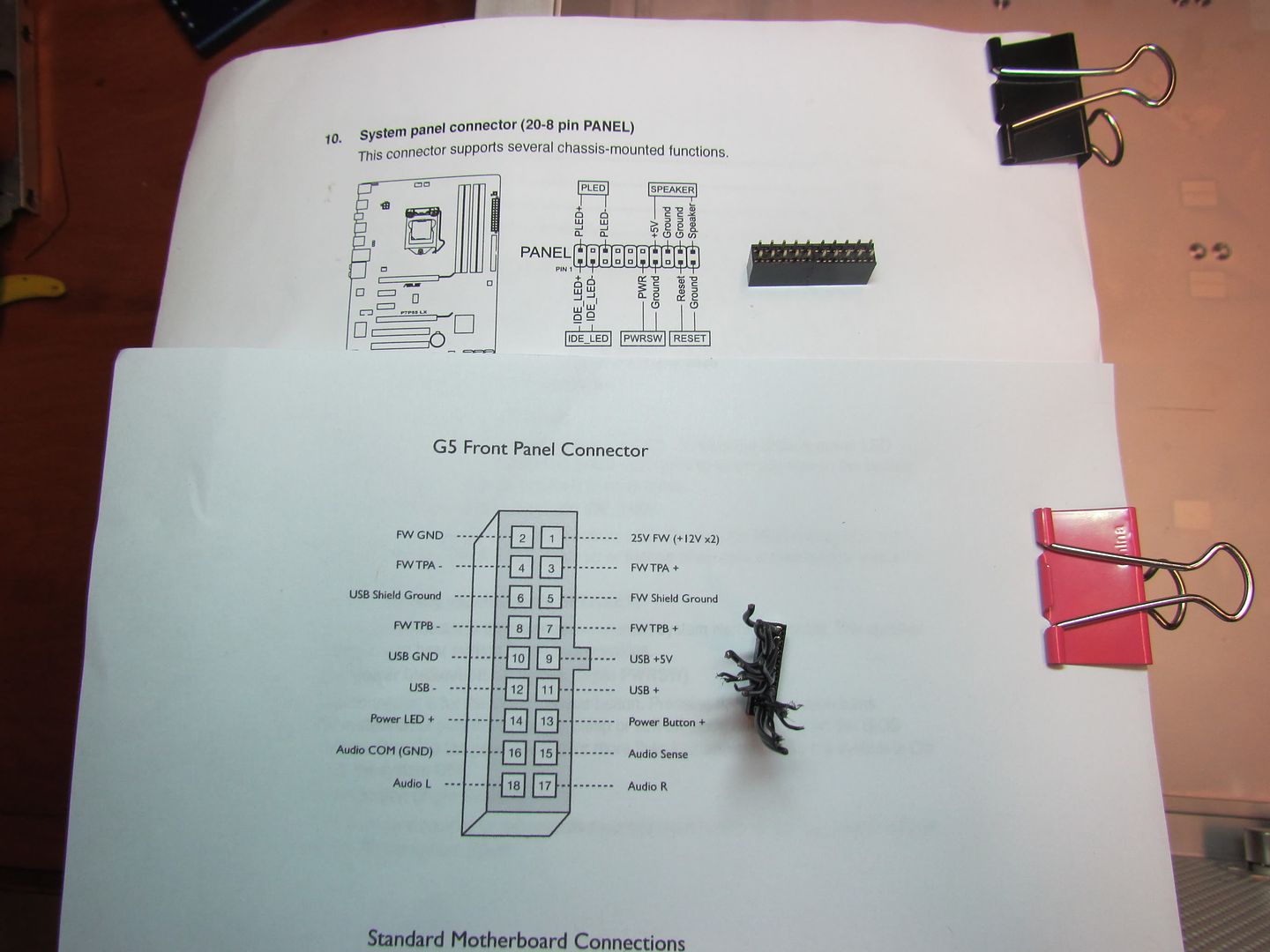
In between coats of paint, I worked on soldering up my front panel adaptor, using some 24 gauge speaker wire and some 5x2 female headers to plug into my motherboard.

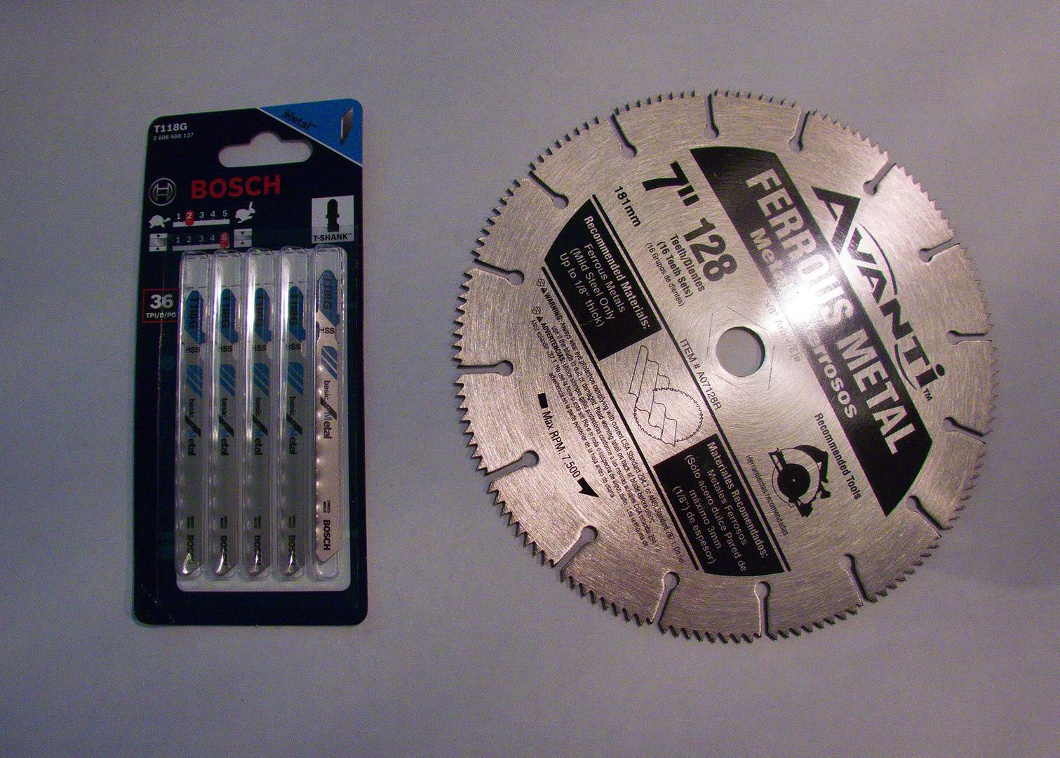
Here's my parts and reference sheet

IMG_3043.jpg


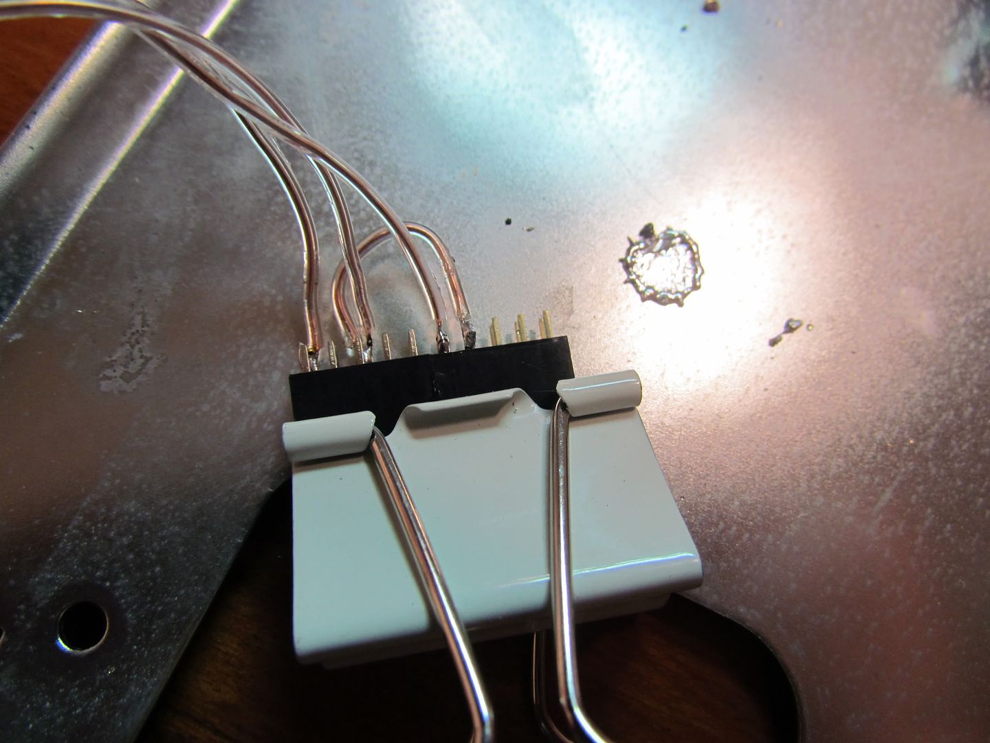
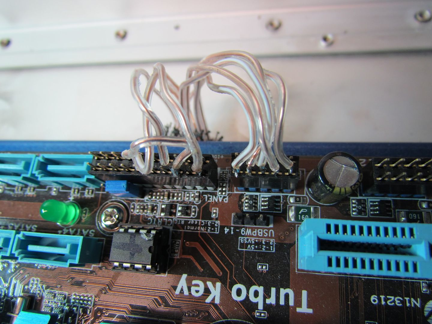
And the soldered main header(i glued 2 headers together.) This gives me a power button and power LED. in addition, my pc speaker is a 4 pin plug that can just plug into the header, so I didn't bother soldering it, and it isnt pictured.

IMG_3045.jpg


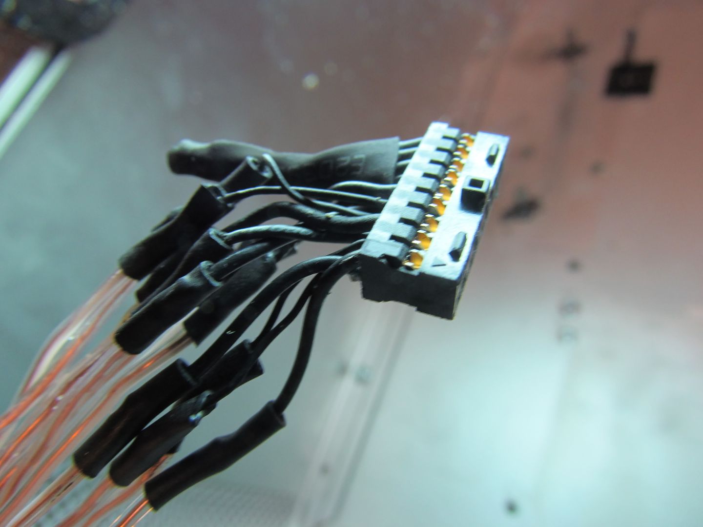
And the mac side of the cable, all done up. I just put some heatshrink around the unused FW wires, just in case I ever get a different mobo with firewire support.

IMG_3046.jpg


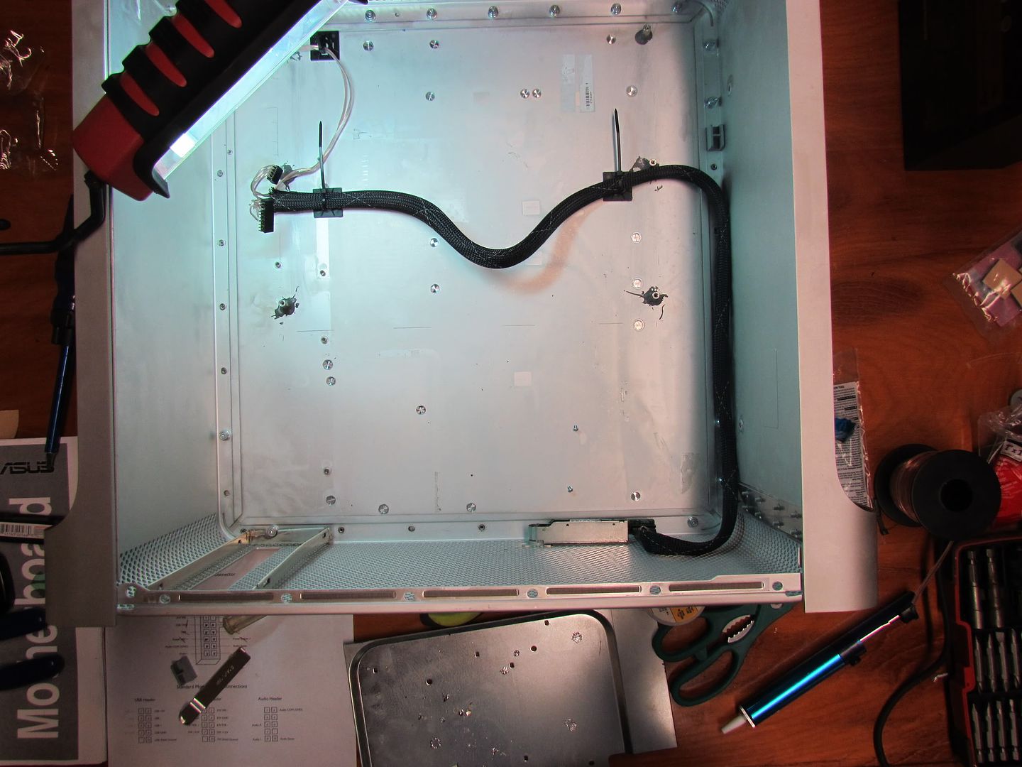
After that was done, I used some wire tie pads and some wire sheathing to make everything look nice and neat when done. That, and it lets me hide that extra 3 inches of slack under the motherboard.

IMG_3048.jpg


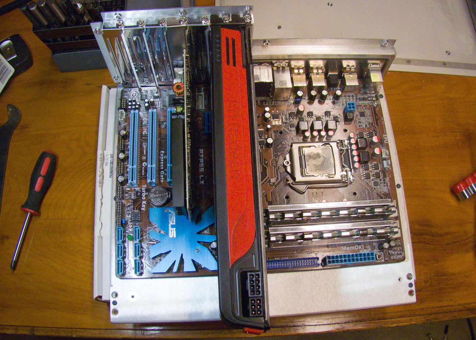
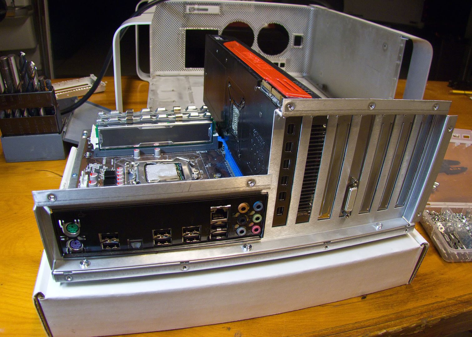
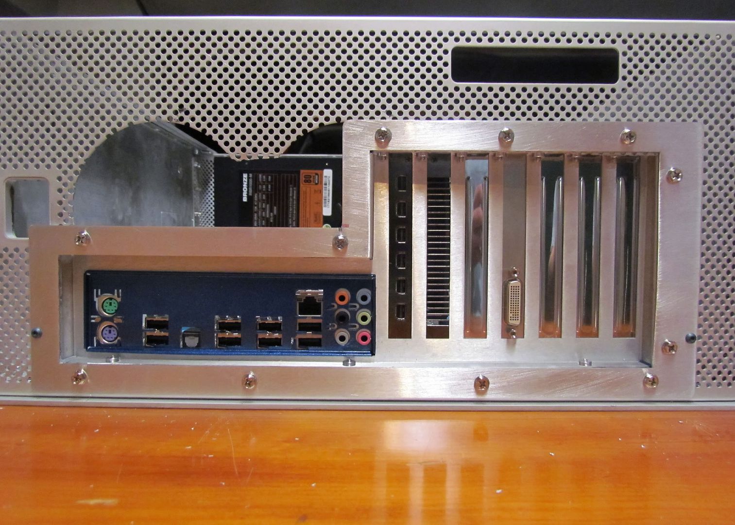
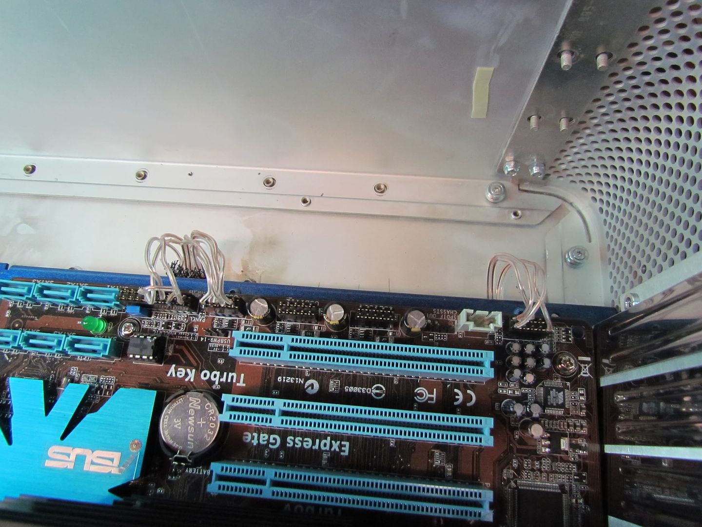
Here is what the motherboard looks like with the main, usb, and audio cables plugged in.

IMG_3049.jpg


IMG_3050.jpg


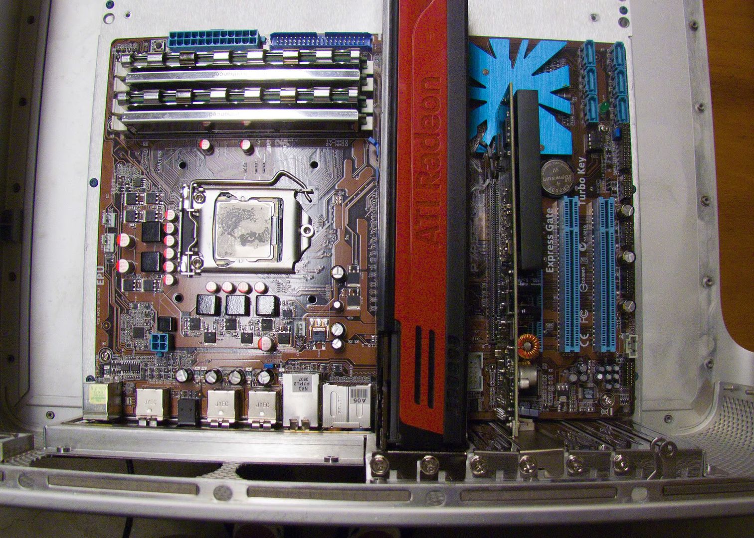
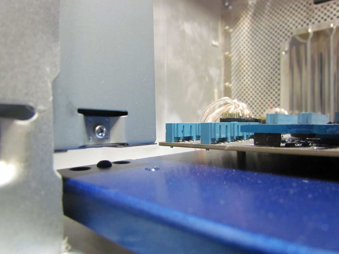
After the wiring was done, I decided to bolt in the blu ray drive too. Boy was I really lucky! The blu ray drive was a bit longer than the cd drive I tested with, and it literally just fits!

IMG_3051.jpg


IMG_3052.jpg


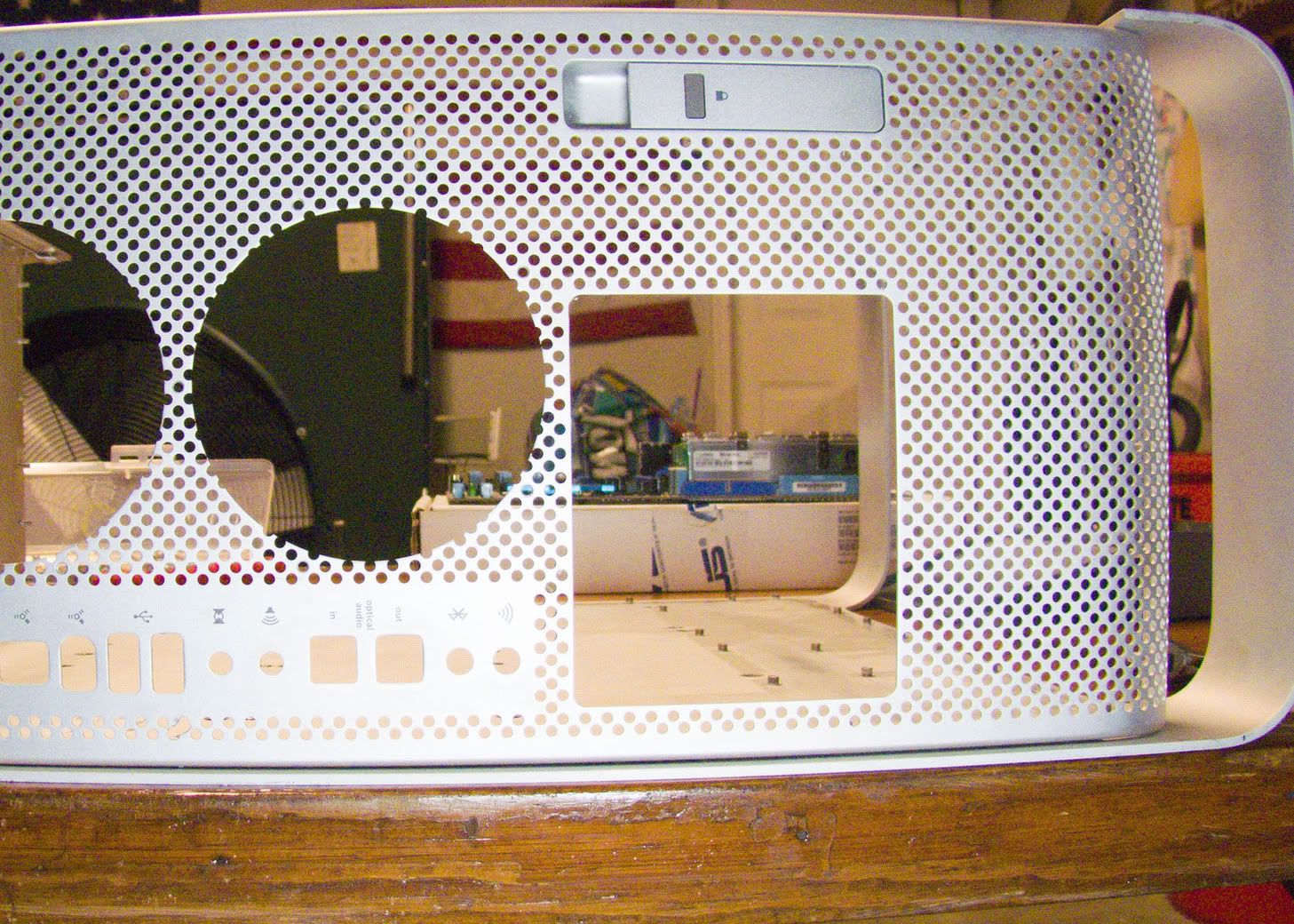
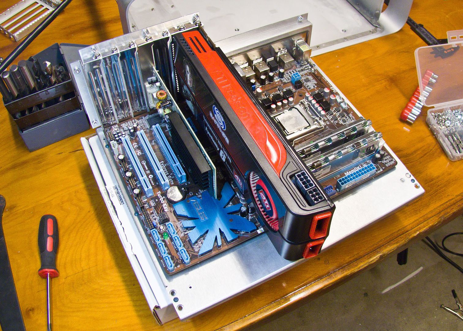
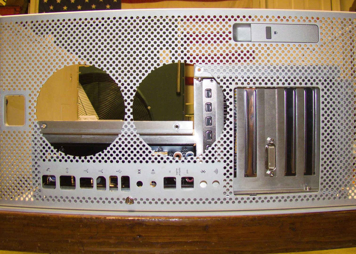
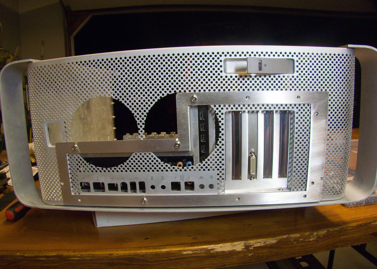
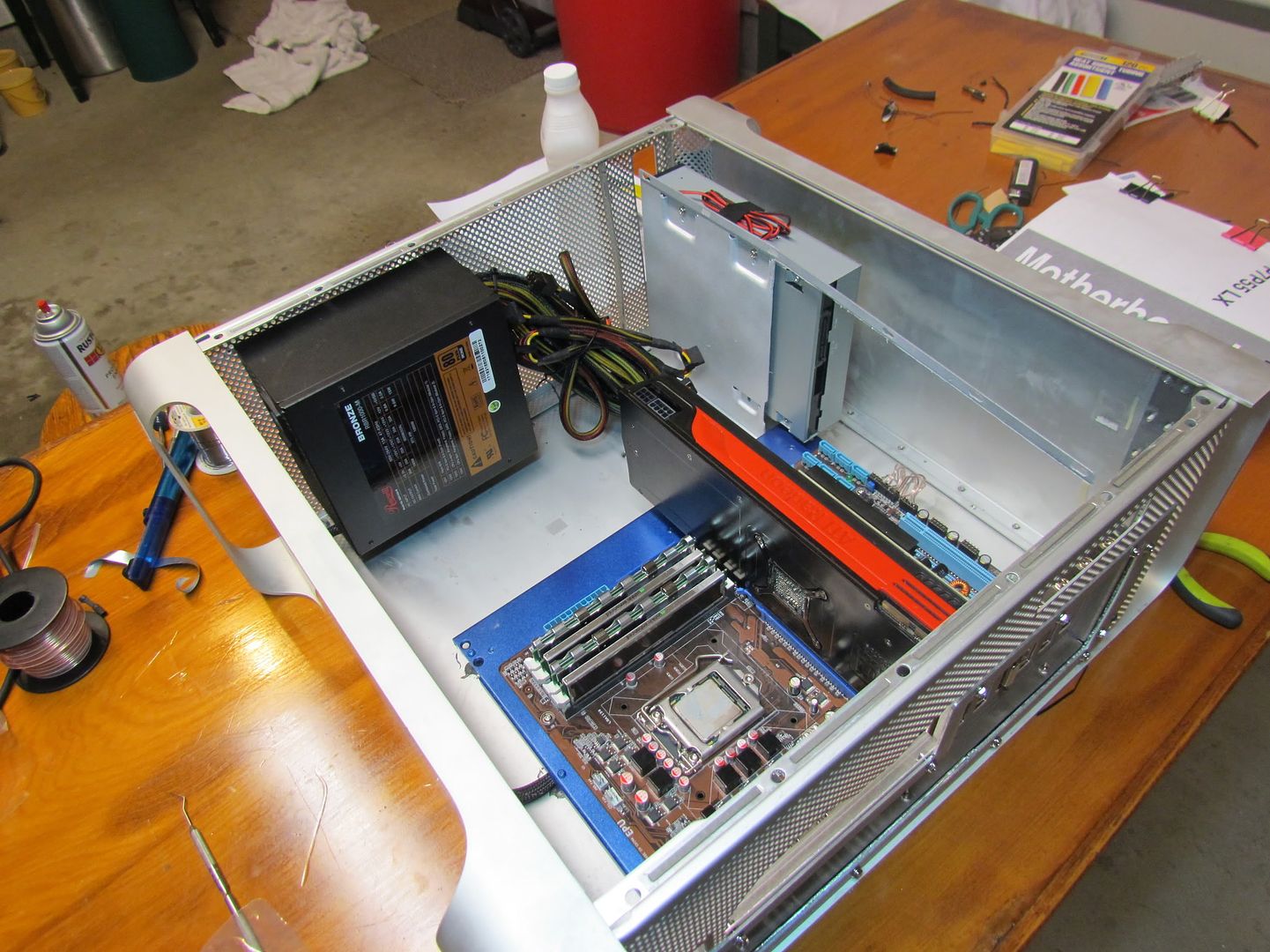
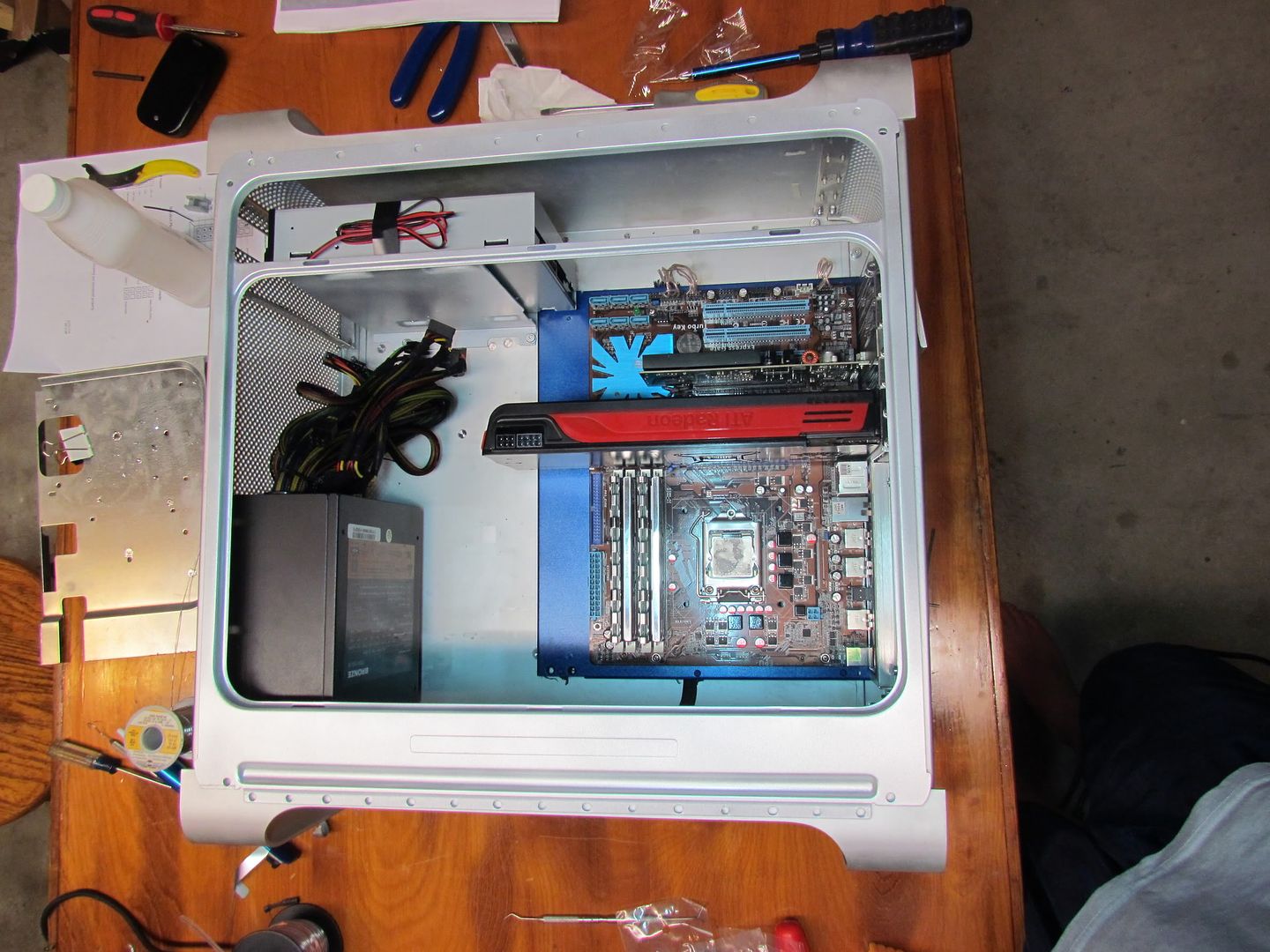
And so that was all the work I could do last night before I fell asleep, so here is the overview so far!

IMG_3053.jpg


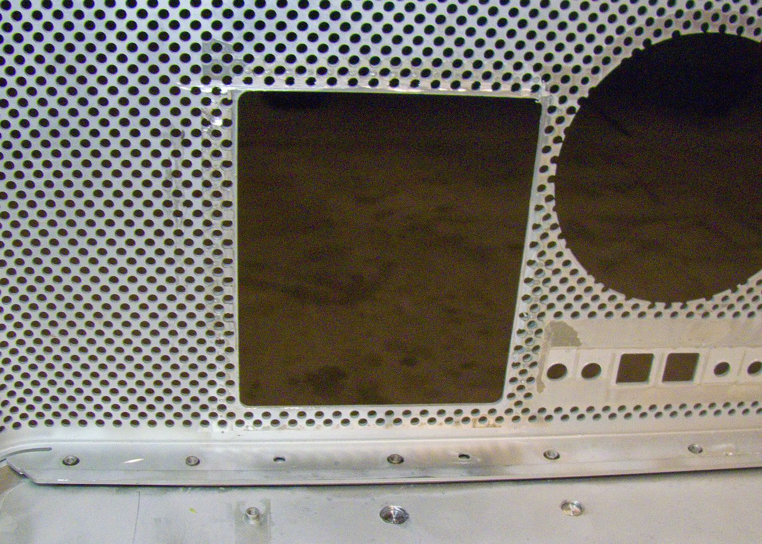
And here it is with the ugly metal front piece that the latching mechanism attaches to. I painted that too. I just need to disassemble the whole thing to actually put it in!

IMG_3055.jpg
 
thats coming on quite neatly so far.
 
samisnake said:
thats coming on quite neatly so far.

Why thank you. I get to meet some Apple engineers and technicians who work in my company when I head up to New York tomorrow. I'm going to see if they will happen to have any decommissioned G5's so I can patch up my hole.
 
Status
Not open for further replies.
Back
Top