Contribute
Register

Project: Quicksilver Power Mac i7

Status
Not open for further replies.
Oh... this make me want to refresh my build. Maybe in a few weeks I'll going to put the case in a better way. The sad thing, my hack died a month ago. The processor and mobo burned, so, now I have more time to do it.
 
OMG, Just one word: Flawlessly!!!
 
Thank you everyone for your kind comments! It's been a busy couple of weeks, so I haven't been able to keep this updated, but it has been a productive one as well.

With all the big pieces of the liquid cooling system in place (aside from the CPU water block of course), it was time to start running the tubing. This was a bit of a challenge as the spaces are very tight to begin with, and made even tighter with all the extra hardware being crammed in. I also had to be careful that the hoses didn't make any bends that were going to be too tight or run the risk of a kinked hose crippling the system and take into account the extra slack that would be required for the door to open and close properly. The solution I finally settled on was to loop them around either side of the radiator for some nice wide curves. This also lets them cross the hinge at an angle so they will be less likely to kink when the door is closed. I added anti-kink spring coils to the outside of the tubing, both because I like the look and because it seemed practical.

7753190086_b9386f04f0_b.jpg


At this point, I put the hard drive bracket in the rear bay (the only one that will not be obstructed by the new cooling system) and started loosely attaching cable bundles to the zip tie mounts. There isn't much space between the drive mount and the radiator, so cable management will be important.

There are three SATA cables that need to run to the top of the case: one for the optical drive, and two for the SSDs. These need to run through the channel with the hose and power cables as well, so I needed to get them bundled together before I could tighten down the zip ties. With the zip/SSD bracket attached to the underside of the optical drive carrier, I carefully taped them all together and then sleeved them as a single bundle with a mesh cable sleeve.

7753194302_d0a5baaba5_b.jpg


Now that all the big cuts and pieces of the main chassis had been installed and I wouldn't need to be working with it in all sorts of weird angles anymore, I decided it was time to reattach the side door. A rivet gun makes this nice and easy and pretty much identical to the original construction. Apple used a LOT of rivets along this hinge... another sign of quality construction as it's extremely solid.

7753190626_9e5a193664_b.jpg


As you can see, the extension cables for the 12V EPS connector as well as the fans are going to be routed under the motherboard so they'll be nicely hidden. Space is a bit tight, but the standoffs are pretty tall so it should work fine without obstructing the hinge mechanism.

7753191156_2e999f3630_b.jpg


With the side door attached and plenty of extra tube length on both hoses, the next step was to finally install the motherboard! I needed to actually mount the water block and route the hoses around the various other components in order to get an exact measure of where the tubing needed to be cut. The water block retention bracket created a couple of issues clearance on the backside of the motherboard and I had to reroute the 12V cable, but it all fit together as planned. Next, time to drop in the CPU and attach the block!

7753195934_fbf31506f2_b.jpg


At this point, I also installed the graphics card so I could route the hoses accordingly. Fortunately, it all fit together as planned, so I cut the tubing at the right lengths, attached to the nozzles, added a thin layer of Arctic Silver, and tightened down the water block.

7753191948_5cdaeca5cc_b.jpg


With all the pieces in place, it was time for the moment of truth... would the side door close properly without kinking any hoses or hitting any obstructions, or had all my planning been flawed? Fortunately, no epic fail occurred, and it all fit together perfectly!!

7753191626_05ef65e109_b.jpg


Since it all fit together without issue, and I am not planning to add anything else to the liquid cooling loop, I decided to fill the reservoir and start working the air out of the system. After checking all the connections again to make sure there were no obvious leaks, I turned the case on its side and added the coolant.

7753192514_f101ffc0cd_b.jpg


With the reservoir topped off and the fill port shut, I mounted the exhaust fan on the radiator and tightened down the zip ties. In order to get the air out of the system, I connected the pump to a spare ATX power supply and jumped the appropriate pins with a paperclip. This allowed me to run the liquid loop without powering anything else in the computer so that, in case of a leak, nothing had power going through it to short out. It also served as a good burn-in for the pump without any risk of overheating components if something in the system wasn't working properly. Every so often, when a big enough air bubble accumulated at the top of the reservoir, I'd open it and add more coolant. It only took an hour or so to get all the bubbles out of the system. I'm very pleased with the neat cable bundle running down the back side of the case and between the radiator and hard drive sled.

7753194802_3e44f3b6d1_b.jpg


While the cooling system was humming along, I turned my attention to the rear plastics that needed to get modified for the power supply connections. First, I cut a Post-It note down to the exact size of the power socket and attached it to the socket. Next, I put a piece of much sticker double-sided tape on the other side of the Post-It, then put the rear plastic on and pressed it onto the back of the power supply. As expected, the Post-It rectangle stuck to the plastic when I pulled it away, leaving the exact location where the cutout would be needed on the plastic panel. I traced this with a Sharpie and then masked off the surrounding areas with masking tape to avoid damaging them while I cut the opening. I wanted the corners to be nicely rounded, so I found a drill bit with the same diameter as the corners of the socket.

7753192956_5ea67fe6b0_b.jpg


Using a drill-press, I drilled a hole in each of the four corners and then cut between them with the Dremel on low speed. Once the basic opening was cut, I used a very small and fine file to smooth the edges and make a smooth transition into the corners, then used 1500-grit sandpaper to smooth the opening out and shine up the edge. This was the result:

7753193466_b55bcfdcef_b.jpg


And with the plastic screwed on over the power supply:

7753193960_85e198f5a3_b.jpg


I'm generally very happy with this, although the power socket is slightly recessed in the opening. This is because the outer layer of the plastic does not sit flush against the metal chassis on the G4s. The original Apple socket cutout, which now surrounds the rocker switch, is molded in such a way that it sinks back to get around this. Unfortunately, there isn't any way for me to replicate this short of fabricating an entirely new plastic piece, so I am content with my results. The power cord fills the entire cutout I made when it is connected, anyways. You can also see in these pictures that I removed the serial number sticker... I'll be making a new one to replace it soon enough.

And that's it for tonight! Next up, it'll be time to start reassembling the exterior of the case and getting everything up and running!
 
Hi, Very impressed by the work you've done so far, it so happens that my boss wanted to throwout a G4 QuickSilver and i decided to take it and do to it exactly what your doing to yours.

Problem is I'm good at design but not very tech savvy. I seen your parts list and thought i could follow along but some of your procedures are beyond my skill level.

If i send you pics of my comp is there a barebones tutorial you can send me to help build a machine like yours. any help is appreciated and even if its a link to another tutorial

Thanks for the time
 
mt3dartist,

Thanks for the comments and I do fully encourage you to build your own, but I'm afraid there isn't much in the way of a tutorial when it comes to case modding. It's all about figuring out what you need the project to do and balancing this with the practical considerations of what fits and doesn't. Modding any Mac case is going to require a lot of cutting, shaping, and reconfiguring of the internal pieces... and this is especially true of the G3 and G4 cases, being much more compact and having a lot less clearance for parts than a G5 or Mac Pro.

Don't underestimate your own abilities, though! This is the first real casemod I've ever done and I'm very happy with the results. It takes a lot of patience and an eye for detail, but the only way you'll know what you can do is to try it. I stared at the empty G4 case on my workbench for weeks before I made the first cut, visualizing and planning different ways to solve problems, and the planning is really the key. Like I said, there really isn't a step-by-step tutorial, since everyone's work is different and there are many ways to tackle a project like this, but this thread should give you a pretty good idea of what major obstacles you're likely to run into. Of course, I'd be happy to give you advice on any particular things you run into as well.

The one big thing I'd recommend to anyone looking at doing something like this is to consider a mini-ITX board. I went with mATX because I wanted the expansion options and the ability to use my existing 1366 CPU, but a mini-ITX build in this chassis would eliminate the need for most of the modifications. I've got a graphite G4 at home that I'll probably be doing this with at some point, but if you want my honest opinion that's the easiest way to go. Good luck though with whatever route you decide to go and I look forward to seeing what you come up with!

Also, I have a lot more pictures and progress to post after the weekend. I've got no wifi where I'm staying for the weekend, and I can only handle so much iPhone posting!
 
tviolation,

Thank you for the reply, you instilled enough confidence in me to attempt this on my own.
i guess because this is my first attempt Ill learn a lot in the process. Ill keep you updated on my progress and would like to thank you again for helping me with my first build.

P.S just two questions before i get started, what is a decent mini itx motherboard to use for 3d modeling and Graphic Design?

Also i keep hearing about ESD how did you combat the electrostatic shocks while building? or is that not a factor yet
 
mt3dartist,

I'd suggest checking Tony's recommended builds and using one of the CustoMac Minis as your specs if you want to go the ITX route. They're well supported and should be stable with a minimum of fuss.

As for ESD, well... it's one of those things that I should be more concerned about than I am. When you've built enough computers, you just kind of learn that it's one of those things that's really bad but happens less than people would have you believe. That's the main reason I use junk parts while I am test-fitting, though. They have the same dimensions as the parts I will really use, but I don't care if they get damaged. When you're actually assembling the computer, make sure you're grounded and use an ESD wrist strap.
 
As I've been experimenting, I decided that I was getting pretty disappointing range out of the internal Bluetooth. I'm not sure if there is something wrong with the MacBook antenna I was using or if it's just attenuating from being too close to the metal chassis, but my Magic Mouse is noticeably laggy at times even at about four feet from the Mac. Other times it works fine, but either way it was enough to drive me nuts. So with this in mind, I set out to redo this part of the mod.

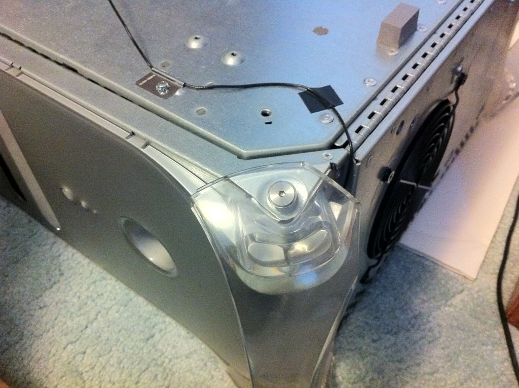
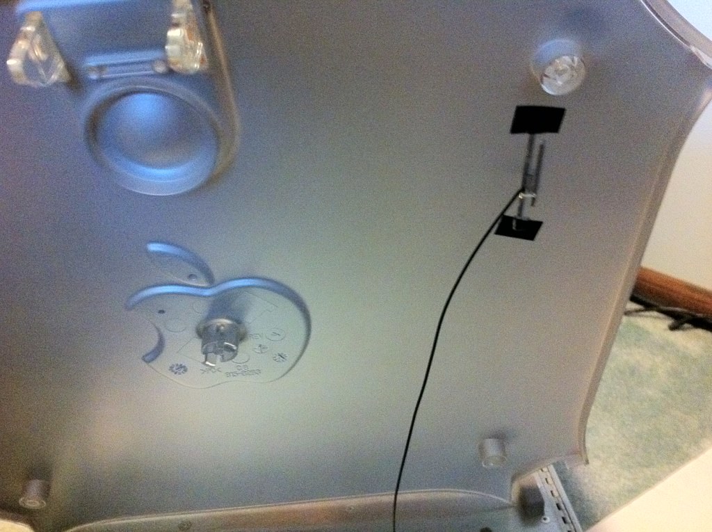
Initially, I had thought of using the G4's original AirPort antennae, but this looked like it was going to be troublesome for a few reasons. One, the metal antennae were in direct contact with the chassis on either side of the case, which I was pretty sure would produce the same problems I had seen with the smaller Bluetooth antenna. Also, the connector was completely different and soldering the tiny wires to make it connect to the Bluetooth board, while doable, was going to be decidedly a pain. So I instead opted to use a single antenna pulled from the wi-fi system of a 17" HP laptop which already had the correct connector and plenty of wire length. I spent quite a while experimenting with placement options, but eventually decided to put it in the same location as the original right-side AirPort antenna, attached to the inside of the plastic panel to keep it as far off the chassis as possible.

7753196514_e729b6c615_b.jpg


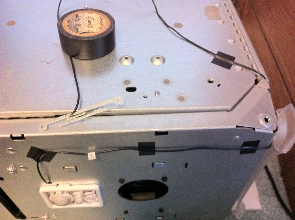
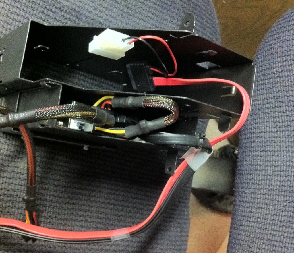
I routed the wire along the outside of the chassis and crossed the hinge in the same groove that the original AirPort antenna wire had, and even used the same wire mounts. I figured that Apple had engineered this to avoid stressing the wiring, and it would allow it to be neatly hidden under the plastics. Once the front panel was reattached, it's completely hidden from view.

7753196766_9dcd13595c_b.jpg


I looked at a bunch of different ways to mount the antenna, trying different materials like plastic, rubber, and foam core as mounting pads to see what would give me the best reception. Ultimately, I decided that the simplest solution was best and used electrical tape to attach it to the plastics. Perhaps not the cleanest solution, but it's completely hidden from view and makes it easy to remove if I come up with a better way to engineer it in the future.

7753197248_1dc362f081_b.jpg


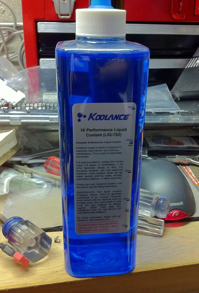
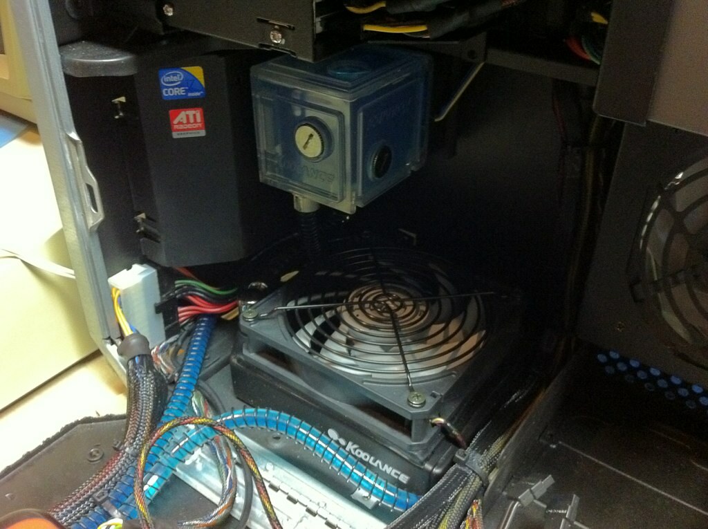
Also, having run the machine for a couple of weeks in a basically finished configuration without the plastics attached, I realized that the pump was making a bit more noise than I'd like, and purchased a pump speed controller. Using this, I was able to drop the pump down from 12V to 8V which made a 
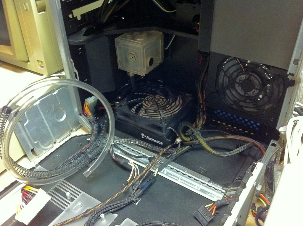
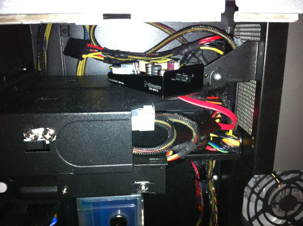
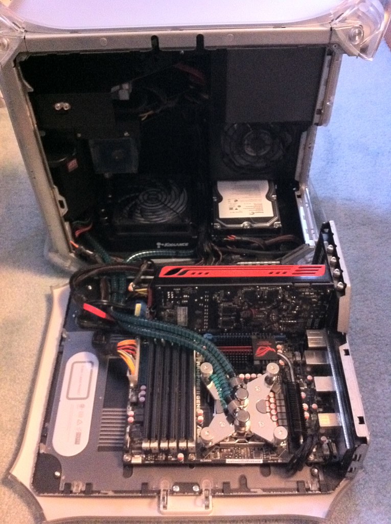
huge difference in the noise level. Amazingly, it actually dropped my average temps a bit too... I am guessing that the extra flow wasn't needed for cooling, and the higher pump speed was actually adding more heat to the system. Either way, I am quite pleased with the cooling performance and mounted the Koolance pump controller inside the case in the open space above the optical drive bay.

7753199868_a61cd58393_b.jpg


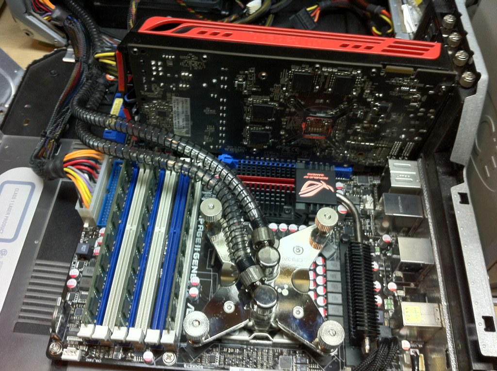
I still need to do some further wire management, particularly with the SATA cables, as they have a little more length than is needed and aren't quite up to my ideals at the moment, but everything overall fit together pretty well. Here's a shot of the case with the side open and all the components installed.

7753199452_79dfa20ef5_b.jpg


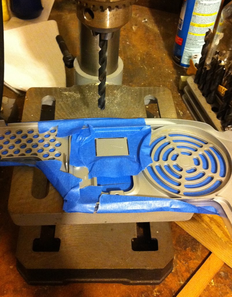
One thing I hope I NEVER do again is resurface the outer plastics of a G4. It was easily the most tedious part of the whole project. Since the Mac wasn't exactly in mint condition when I received it, I decided to completely resurface the plastics. I'd used the Novus plastic polish system on my G4 Cube previously with amazing results, but what I didn't take into account was that, unlike the Cube, the G4 tower's outer shell is polycarbonate rather than acrylic. This material is MUCH harder and takes a lot more elbow grease to polish. Nevertheless, having a super-shiny Mac was important to me, so I went ahead with it. I started by sanding both side panels with 400, 600, 1500, and 3000 grit sandpaper in that order to remove all the deep scratches and scuffs, then went through the three steps of the Novus polish to restore the flawless gloss finish. I can't even tell you how many applications and buffings with the plastic polish I used, and it's still not perfect. After a while, I got it to the point where all that remained were hairline swirl marks from the buffing cloths which are only visible under harsh direct light and decided that it was good enough to reassemble.

7753198528_61b0e62746_b.jpg


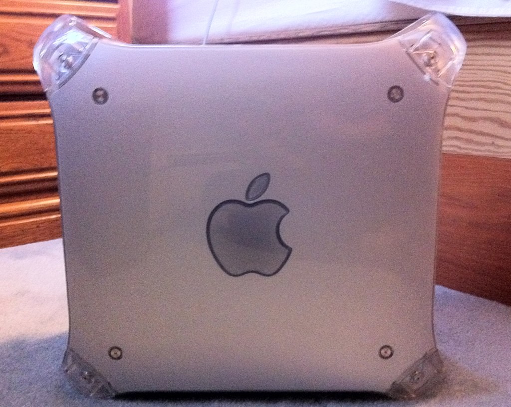
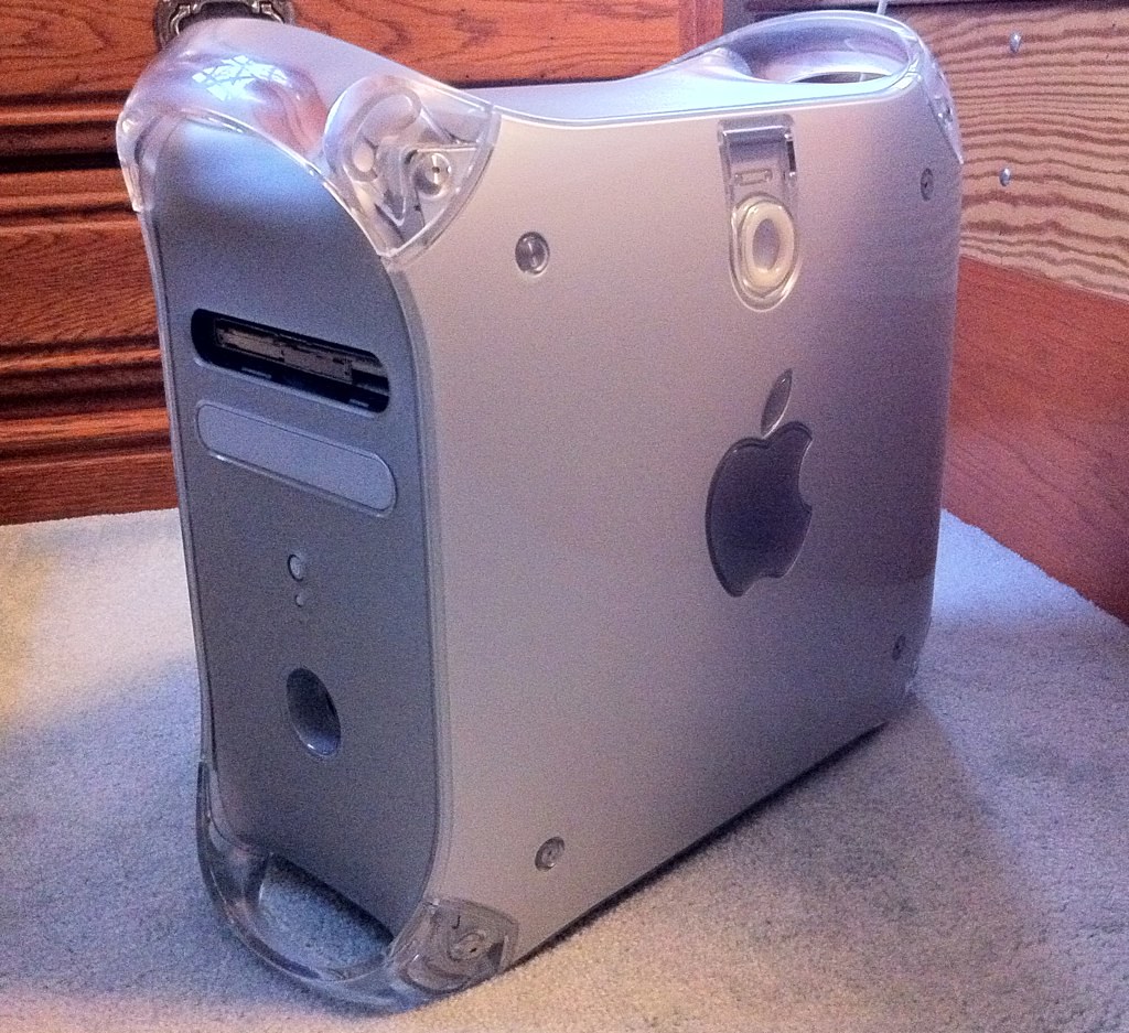
From the side, looks just like a Power Mac G4. :D 
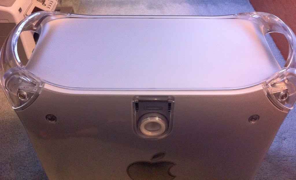
And best of all, from the top, no blowholes!

7753199004_c2d09214e8_b.jpg


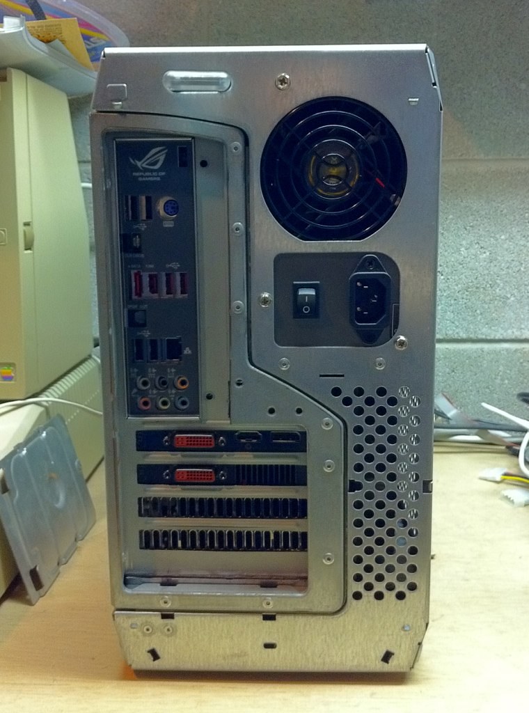
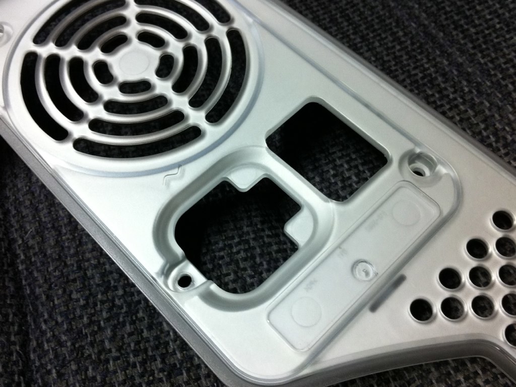
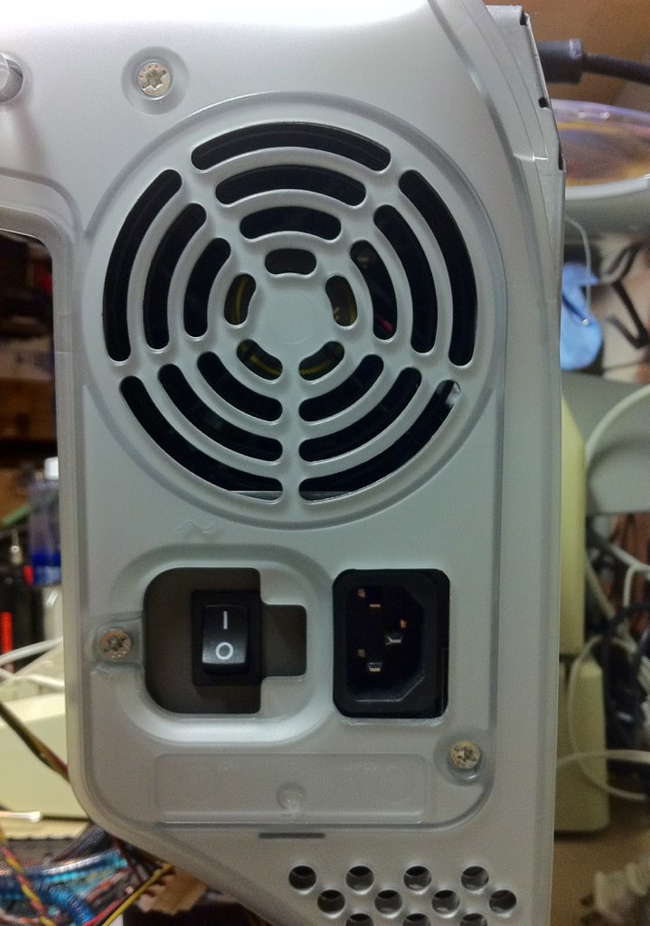
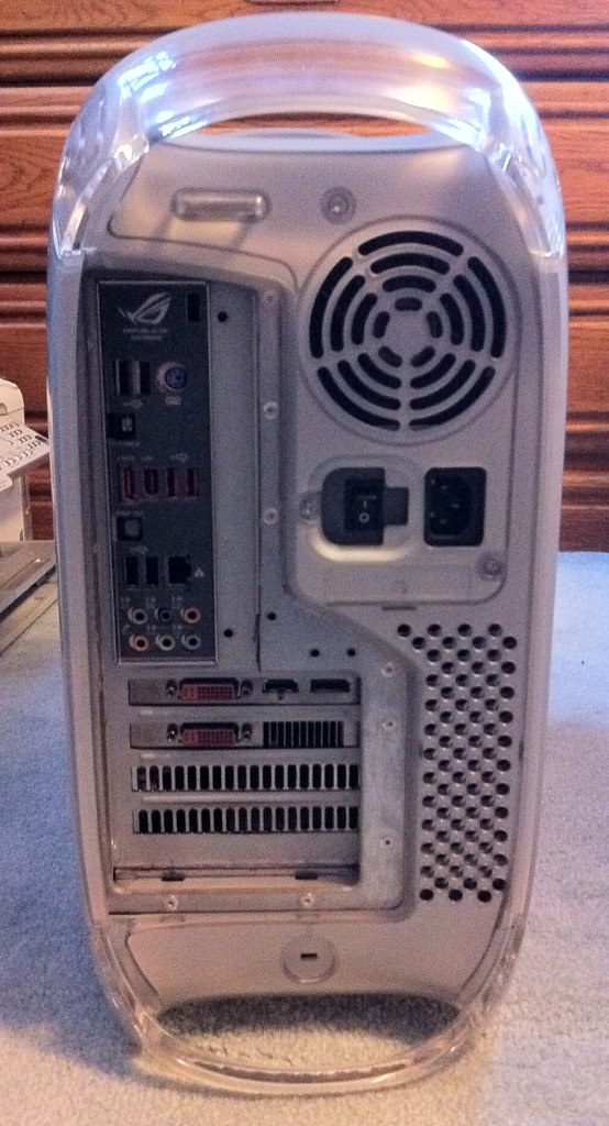
From the back, it becomes obvious that it is no ordinary G4. I still haven't quite finished reworking the plastic trim that goes on the back of the I/O cutouts, so it hasn't been attached yet. That'll be coming soon, but it isn't bad without it either. The latch mechanism at the top still works normally and can be used to keep the side door from opening with a security cable or padlock, though I don't have any use for this feature at home.

7753198066_ea3f551b77_b.jpg


And finally, a 3/4 shot of the assembled computer. You can see the slot-loading optical drive in the top bay is still missing its bezel. I haven't quite figured out how I am going to cut the slot without making a mess of it yet, so I've left it off for now. The drive is functional, though, if not pretty yet. I'm also toying with the idea of reattaching the original drive door and making a release mechanism to drop it down in order to access the slot, as it would require less cutting and make it appear more stock.

7753197596_5da89476b0_b.jpg


So that more or less completes the bulk of this project. The only things I have left to do now are the optical drive bezel and the plastic trim for the back of the motherboard tray. I'll be tackling these in the next few days and will post them once done, as well as some better high-quality (non-iPhone camera) pictures of the whole completed thing. Overall, I couldn't be happier with the results thus far and the completed Mac is running great.

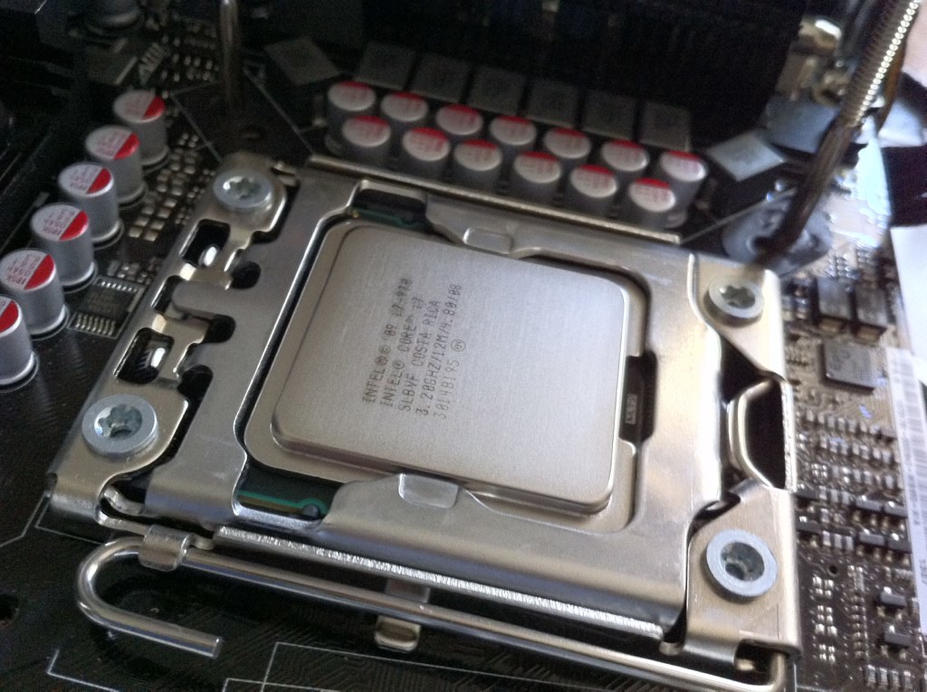
As for the thermal issues with the case design, the liquid cooling system seems to be handling these well. At stock clock speeds (3.2GHz), the CPU idles in the low-mid thirties C. At load, like when encoding HD video in Handbrake, it gets up to the mid sixties. I'm really pleased with these temps and they're actually lower than what I was seeing in the old Antec case with the Corsair H50 and much lower than Intel thermal spec. And best of all, it's almost inaudible at idle and significantly quieter than the original G4 even at load.

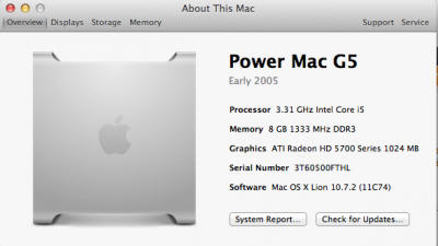
One final thing I want to mention in this post is on the software side of things. I was experimenting with the SMBIOS values while installing Lion and discovered an interesting quirk in Mac OS X that was actually super fun for me. I'm using MacPro5,1 as my system definition, installed from MultiBeast. I thought it would be nice to feed the original Power Mac G4's serial number to the system, just because, and manually entered it into SMBIOS.plist. To my surprise, after doing this, selecting About This Mac/More Info from the Apple menu yields the following screen:

7753200416_4913132fb8_z.jpg


:D :D :D

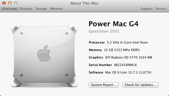
I was amazed by several things with this. First, that Lion apparently bases this screen on the serial number rather than the model identifier, and second that Lion is even capable of decoding the serial number of a 10-year-old PowerPC G4 machine that can't run anything higher than Leopard. Third, that the high-res graphics for the G4 Macs are still included in the OS. Opening System Profiler still identifies it as a MacPro5,1, but I thought this was a neat quirk and a perfect finishing touch for the project. Also, I've never seen this documented anywhere else, and it could be useful for others modding older cases. That's it for today!
 
thought id try it with the serial number of my g5 case, and it did the same thing lol
 

Attachments

  • Screen Shot 2011-11-16 at 19.53.08.png
    Screen Shot 2011-11-16 at 19.53.08.png
    82.3 KB · Views: 1,086
That is AWESOME!

And I have to say that, even as a Mac user since 1998, I would even have to look a few times at the rear panel before I knew it definitely was a hack.

David
 
Status
Not open for further replies.
Back
Top