Things are coming together nicely, and I should be ready to start installing the various computer components this week. While I was test-fitting, I discovered that my motherboard has a vertically-placed CMOS battery next to the memory slots which I hadn't accounted for. And sure enough, it hit the optical drive cage (barely) when closing the door. So again, I went back to the Dremel, and managed to mess up the finish on the Plasti-Dip in the process. Fortunately, it wasn't too bad to peel off, so I was able to make my cuts (giving EXTRA space this time, so that I will never run into this with any future motherboards) and then repainted it.
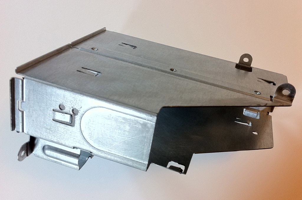
You can see that you really do have to cut a lot off this part of the chassis to make room for the motherboard. There are a few narrower mATX boards out there, but they didn't have the feature set that I wanted, so this is what you get. I also wanted to angle the cut across to make it look cleaner, and to retain the mounting tab on the back.
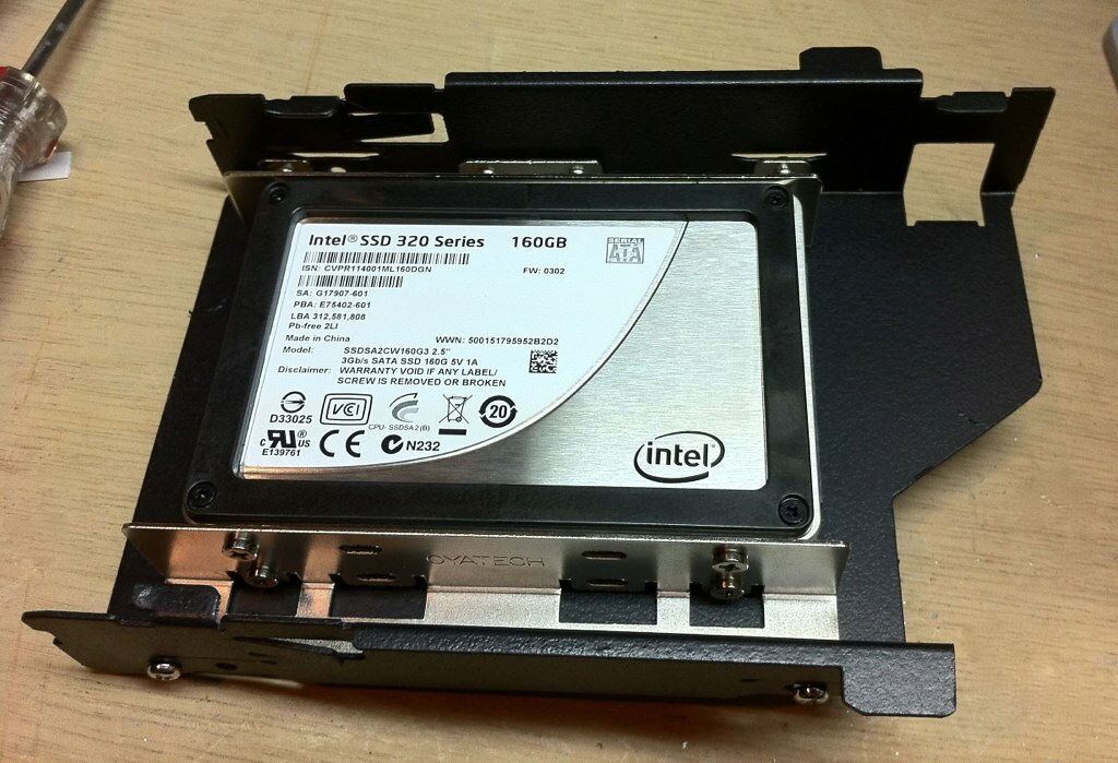
The lower cage, which originally held the Zip drive, also needed to be cut, though not as much as it is already narrower and shorter. I still trimmed as much as I could, since the liquid cooling tubes will pass by here when the door is closed. The boot drives are installed here: a pair of 2.5" SSDs mounted in a dual 2.5" to 3.5" bracket, which will be configured in RAID 0.
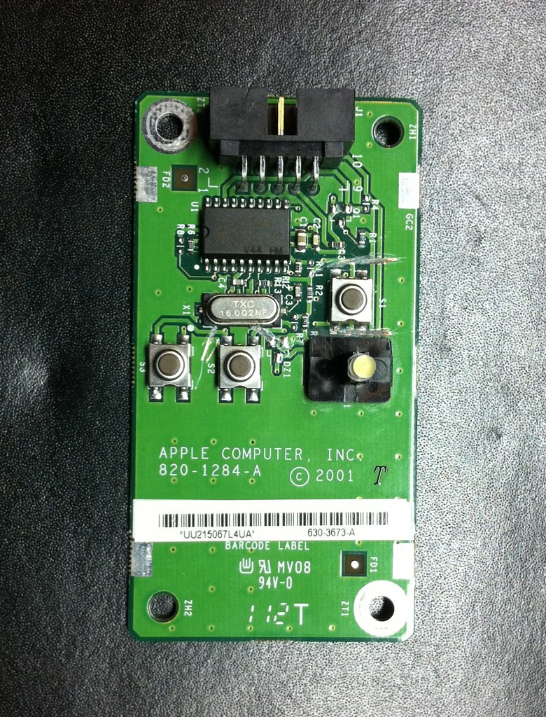
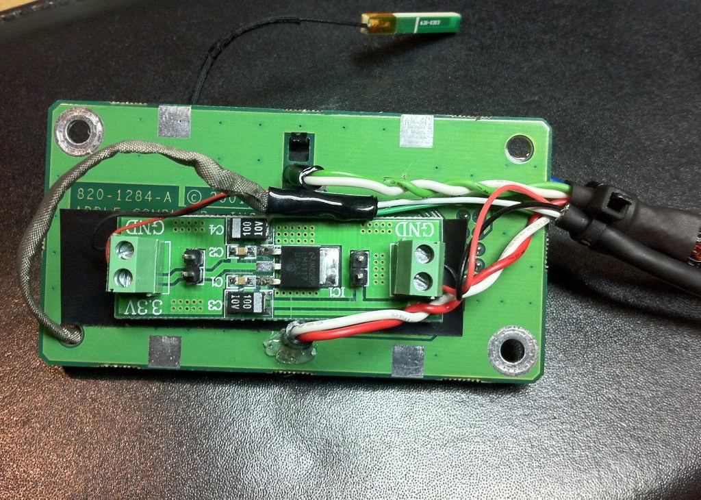
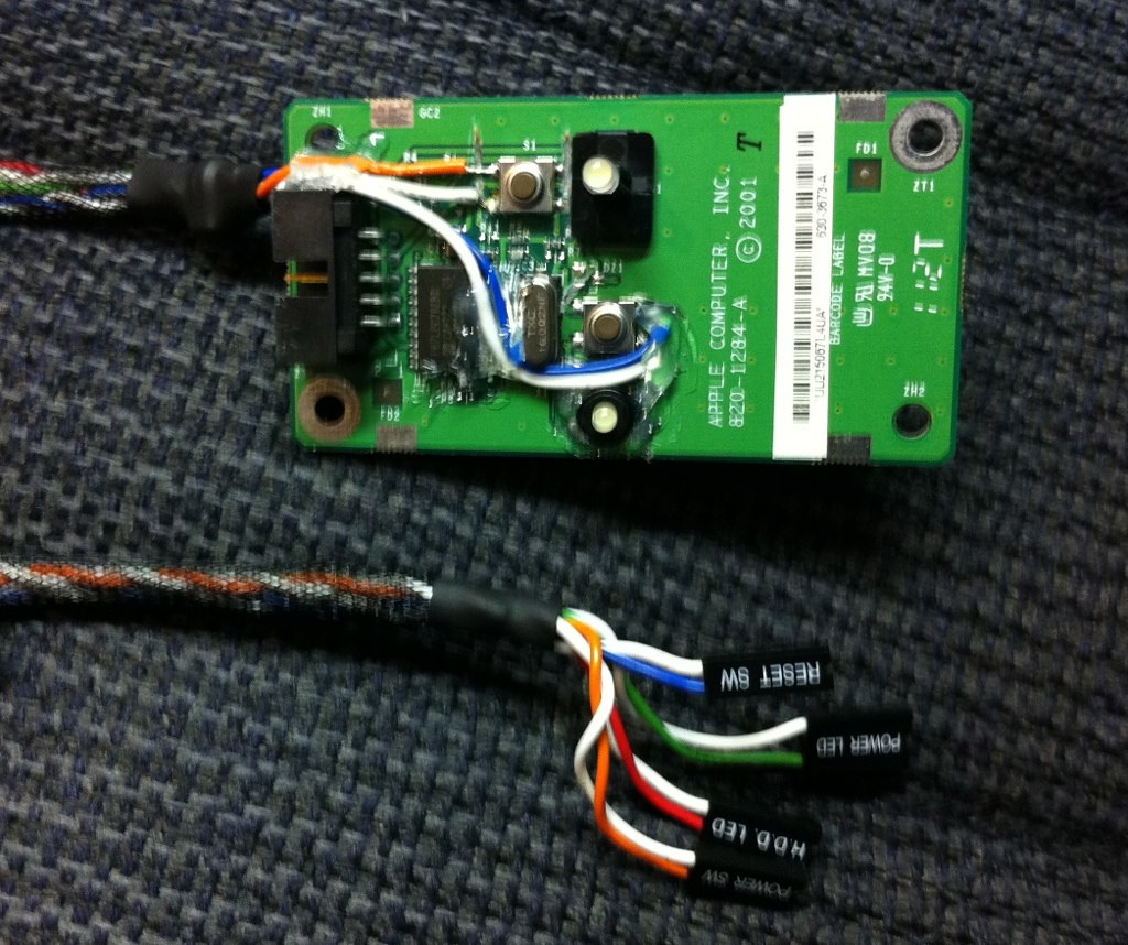
Between coats of paint on the optical drive cage (I find that four coats of Plasti-Dip seems to give me the best finish), I set to work on the front panel board. As you can see, there is a bit of circuitry on the board, as well as the interrupt switch, which aren't really necessary for a standard PC board.
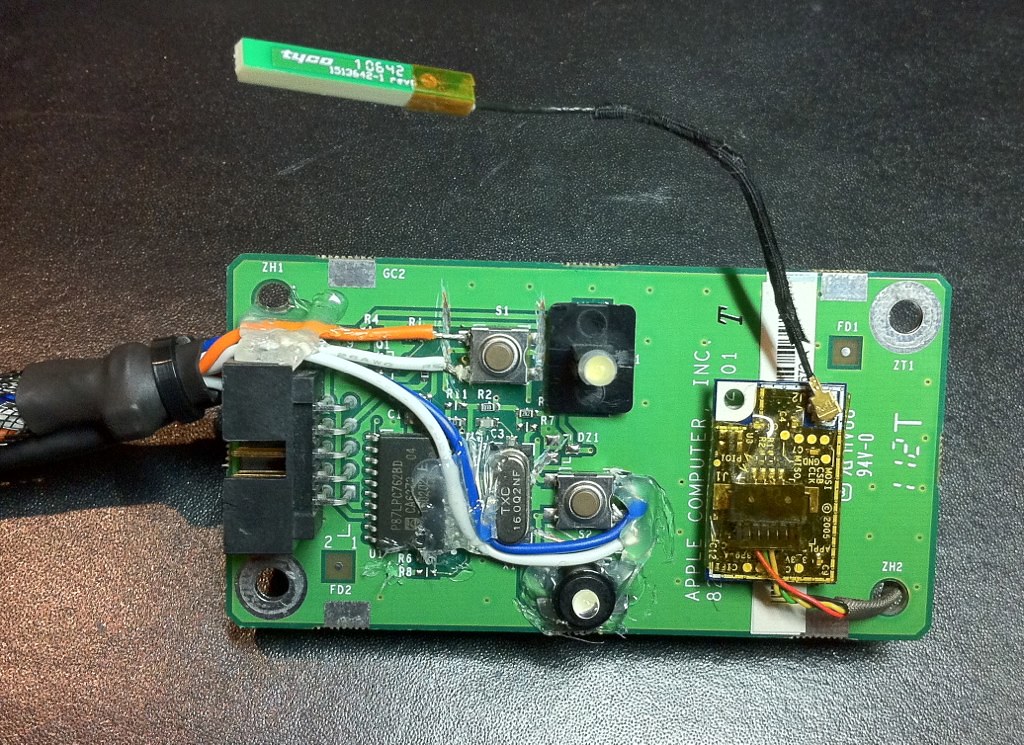
I was originally going to rewire the Apple ribbon connector, hoping that the circuitry was responsible for the pulsing sleep light and that I could retain this functionality. Unfortunately, research proved that this is a function of the motherboard, not the front panel board, and that the pinout on the ribbon gave a number of incompatibilities for a PC motherboard. So instead, I cut the circuit traces with a file to avoid any shorts and soldered regular front panel connectors directly to the components. I also removed the interrupt switch and mounted what will become the hard drive LED in its place, then sleeved up the wires so they would look nicer.
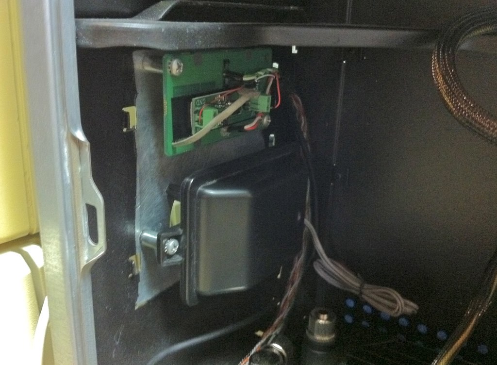
One of the plans I have had all along was to wire up an Apple Bluetooth module (pulled from a white MacBook) and put it in this build using the excellent guide on this forum. I've been trying to decide where to put it for a while, because one of my goals has been to put the antenna outside the chassis but under the plastic shell in order to improve signal. The original plan was to put it where the AirPort card had been, but I decided this might get in the way of other components and while working on the front panel, I realized there was plenty of extra space on this board.
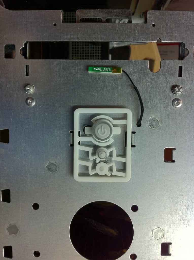
The Bluetooth board fit neatly next to the buttons on the front of the board, and there was even a conveniently placed extra hole in the board to route the cable through. The back of the board was almost completely empty, which was a great place to put the 3.3 - 5V transformer needed.
I drilled a small hole in the front of the chassis to route the antenna through. It JUST fits in the space between the metal chassis and the plastic front panel when attached, which is perfect!
I had wanted to hook the internal speaker to the audio header on the motherboard, if possible, so I could switch it over in the control panel if I wanted to use it. I didn't really anticipate wanting to do this much, but it was one of those nice touches that would have been nice. Unfortunately, when I wired this up, I wasn't able to get any audible sound out of it. I suspect the impedance is just too high, but it's a low priority. I may tackle this again at some point in the future, but for now I just bundled up the speaker wire and mounted it back in place as it wasn't important enough for me to worry about.
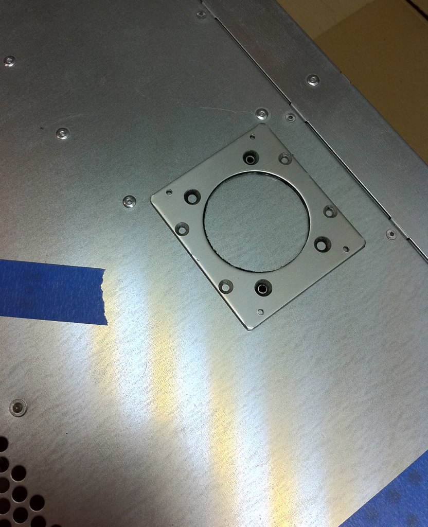
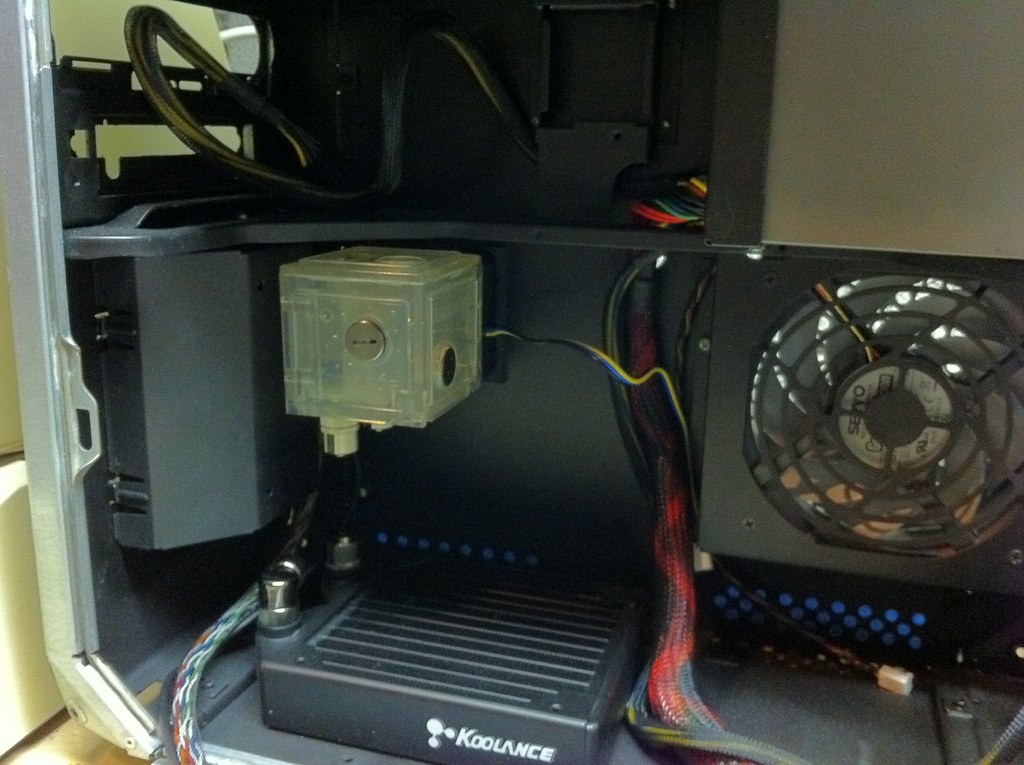
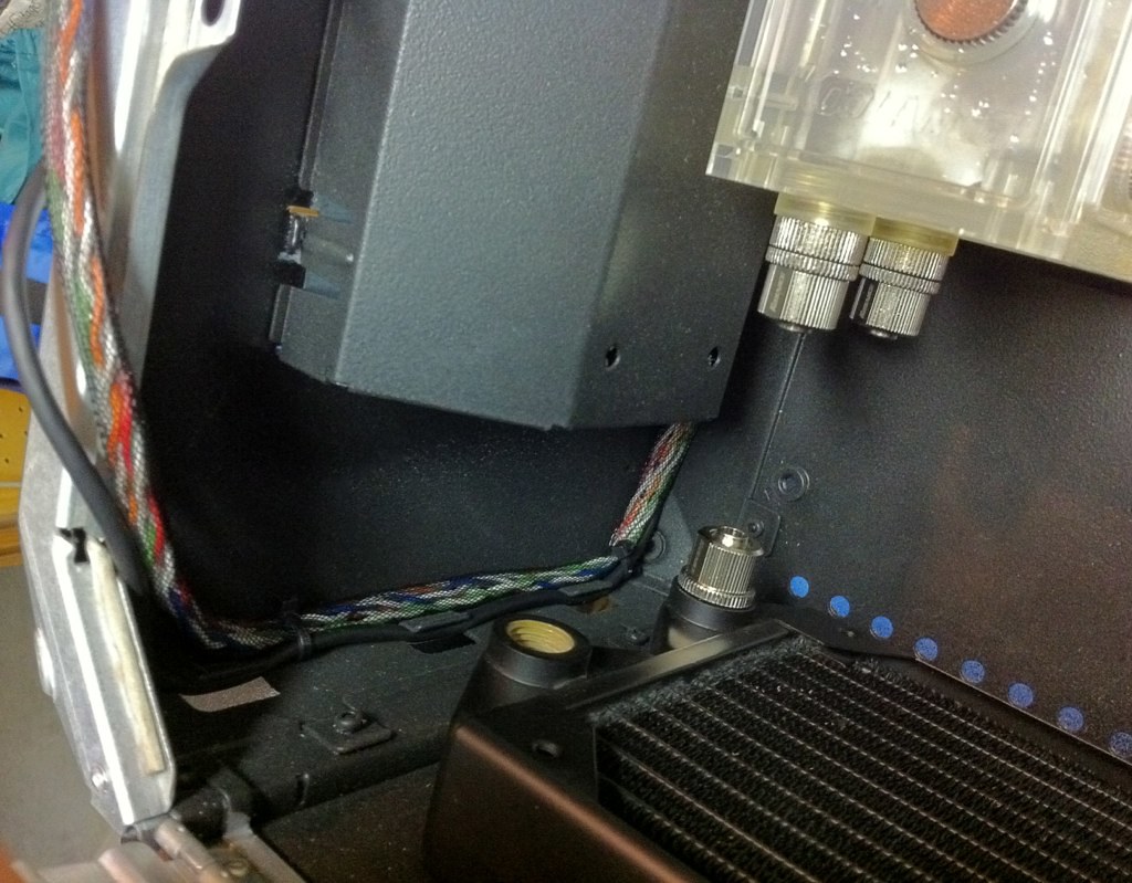
Now that the front panel parts were mounted, I could put the inside enclosure back over them and continue working inside. I decided to mount the pump/reservoir right behind this panel, both for aesthetic and space considerations. This particular unit can be mounted in three different orientations, so I chose the one that offered the easiest routing of the tubing. The pump came with a mounting plate that goes outside the chassis, so I measured and marked this for drilling from the outside.
The pump mounts on a dense foam pad to dampen vibrations. I also rubberized put a think layer of the same material on the underside of the mounting plate, so hopefully this will keep any vibration from transferring into the chassis through the screws that go into the pump housing.
With everything mounted in the front part of the case, I'm able to start cable management and routing everything. The clips which originally held the front hard drive sled seemed like a perfect way to neatly route the front panel cables and the USB header going to the Bluetooth board.
Hopefully, I'll have a chance to start running the tubing for the liquid cooling system tomorrow. And, if all goes as planned, I'll rivet the side door back in place and start installing the computer hardware in a couple of days!