Contribute
Register

G5 USB 3.0 Front Panel and Audio

Status
Not open for further replies.
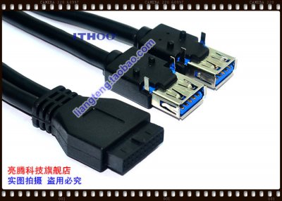
Well if it's going to be dual USB3, then you can count me out. Darn... was hoping to keep it looking stock.

Good luck with your project!

I'll let you know if i ever incorporate FireWire, its just that I'm trying to save a bit on the costs right now since I can't find anyone who's selling firewire in a non bulk method.
 
Time for an update.

So far, I'm most of the way done with the PCB design, I still have to borrow a multimeter from a friend and figure out the 4 Pole Audio circuit.

I've also attached pictures of the cut plastic liner, but keep in mind that I just did this with an xacto knife, so it could be a lot better. The USB you see is just a usb female to header cable that's hot glued to the original apple PCB, and is really janky.

Thanks you guys for offering to pre-order, I'll let you know how much the total is going to be, and for your support, I'm probably gonna throw in a discount of some sort. I'm still reluctant to do the cables as they are wayyy too expensive, but I'll look into what I can do about that issue.


With reference to the audio port. If you do not already have a copy of the Intel spec you can download it here: http://www.formfactors.org/developer\specs\a2928604.pdf

See page 25 figure 6. HD Audio jack

For some reason the jacks with the “make” or normally open contact are hard to find. There is a CUI Inc. part SJ-435107RS that is through hole right angle and best of all there is stock at Mouser, see http://www.mouser.com/ProductDetail...YrfDAUsXybTFDw4vx0TMkJp2NNZgjg421Q08Ml6ofAA==

Data Sheet attached.

Good modding,
neil
 

Attachments

  • sj-435107.pdf
    269.3 KB · Views: 157
With reference to the audio port. If you do not already have a copy of the Intel spec you can download it here: http://www.formfactors.org/developer\specs\a2928604.pdf

See page 25 figure 6. HD Audio jack

For some reason the jacks with the “make” or normally open contact are hard to find. There is a CUI Inc. part SJ-435107RS that is through hole right angle and best of all there is stock at Mouser, see http://www.mouser.com/ProductDetail...YrfDAUsXybTFDw4vx0TMkJp2NNZgjg421Q08Ml6ofAA==

Data Sheet attached.

Good modding,
neil

Thanks for the info Neil, The intel spec should be useful, but that audio jack tat you linked is both expensive, and doesn't have a sense connection, it seems to be straight through.

I plan on using these:
http://www.aliexpress.com/item/50-P...or-6-Pin-SMT-Stereo-Headphone/1713701094.html
They're a lot cheaper, and they have 2 sense pins. I made myself a little adapter that goes to HD Audio to figure out the layout actually and the 4 pin will be adapted from that.
Drawing.jpg
By chance, do you know where I can find these:
IMG_5023.jpg IMG_5026.jpg
I can only seem to find M3 Tapped ones that interfere with everything due to their size.

And possibly the white smd connector for the powerswitch?
 
Thanks for the info Neil, The intel spec should be useful, but that audio jack tat you linked is both expensive, and doesn't have a sense connection, it seems to be straight through.

I plan on using these:
http://www.aliexpress.com/item/50-P...or-6-Pin-SMT-Stereo-Headphone/1713701094.html
They're a lot cheaper, and they have 2 sense pins. I made myself a little adapter that goes to HD Audio to figure out the layout actually and the 4 pin will be adapted from that.
View attachment 129916
By chance, do you know where I can find these:
View attachment 129917 View attachment 129918
I can only seem to find M3 Tapped ones that interfere with everything due to their size.

And possibly the white smd connector for the powerswitch?


Hmmm... You have the circuit wrong. With motherboard HD-Audio you need a contact closure (Sense2), when the plug is inserted, in the front panel jack which make pin 10 to pin 7 in the motherboard header.

This is what the CUI Inc. SJ-435107RS brings to the party. Ref the data sheet and normal open contacts are on pins 5 and 6. The key is the RS version of the part.

Good modding,
neil

edit more added: See my SOS project: http://www.tonymacx86.com/powermac-g5/129400-neilharts-slow-roll-g5-power-mac-system-slides.html

See post #8 towards the bottom. I use the dead bug approach, and epoxied the jack to the original circuit card.
 
Oh great! It will have dual USB 3.0 port. Please count me in as well~~
So will the audio jack identify if there is a 3.5mm audio plugin? And the original power button will be preserved?

Great work! Waiting for your good news~ Thanks!
 
I still haven't gotten around to working on the audio part of the circuit, but in theory, it should detect headphone jacks being plugged in.

As for the original power button, yes it will be preserved, but i can't guarantee the connector or wiring will stay.
 
Hi akhilv1, btw I live in Hong Kong and I may able to help you find cheap cable/connector from China TaoBao. For the 19pin USB 3.0 female to female, it is at around USD 2.5. As the price difference is huge, it may be an alternative for you.

However, will it be more simpler to have a 19pin-to-2USB3.0Female? I found a cable (photo attached) has solder feet to allow itself to be mounted on circuit board.

And found some 3.5mm 4-contact audio jack on taobao for your selection as well:
http://s.taobao.com/search?initiati...+插座+四&suggest_query=3.5mm+插座+四&source=suggest

For the reset button, do you think it is okay to use original "holes" of G5 chassis? Just place a micro switch behind the one hole, and one need to use a paper clip to push it through hole. HDD LED can be the same as well~

Just some idea, not sure if they are flexible or not~ Thanks a lot!
 

Attachments

  • T2sWbqXK0XXXXXXXXX-75283534.jpg
    T2sWbqXK0XXXXXXXXX-75283534.jpg
    124.6 KB · Views: 202
  • T1hjdyXalvXXX7UinX_115514.jpg
    T1hjdyXalvXXX7UinX_115514.jpg
    18 KB · Views: 145
Hi akhilv1, btw, I live in Hong Kong and I may able to help you to get cables or connectors from China cheaper. For the 19pin USB female-to-female cable, it is at around USD 2.5 something per piece.

And when I search for cable, I found 19pin-to-TwoUSB3.0-socket cable. This is also around USD 2.5. Will it be a more simple implementation? (It has soldering feet to mount on PCB as well).

Pls check and comment. Thanks!
 

Attachments

  • T2BBbqXHhXXXXXXXXX-75283534.jpg
    T2BBbqXHhXXXXXXXXX-75283534.jpg
    102.8 KB · Views: 142
Hi akhilv1, btw I live in Hong Kong and I may able to help you find cheap cable/connector from China TaoBao. For the 19pin USB 3.0 female to female, it is at around USD 2.5. As the price difference is huge, it may be an alternative for you.

However, will it be more simpler to have a 19pin-to-2USB3.0Female? I found a cable (photo attached) has solder feet to allow itself to be mounted on circuit board.

And found some 3.5mm 4-contact audio jack on taobao for your selection as well:
http://s.taobao.com/search?initiati...+插座+四&suggest_query=3.5mm+插座+四&source=suggest

For the reset button, do you think it is okay to use original "holes" of G5 chassis? Just place a micro switch behind the one hole, and one need to use a paper clip to push it through hole. HDD LED can be the same as well~

Just some idea, not sure if they are flexible or not~ Thanks a lot!

I'm using that USB 3.0 cable right now but it's really clunky and falls off every few days. The solder points are too far on the cable to be any use but I'll look into using them.

As for the 4 contact headphone jack, not any random jack will work as you need sense and the ones that work are expensive.

You can use a momentary contact switch with a regular hole, but you're goi to have issues wit alignment and placing it correctly. I actually have one lying around, but the alignment issue makes me not want to use it.
 
Status
Not open for further replies.
Back
Top