Contribute
Register

G5 Front Panel Quick Guide

Status
Not open for further replies.
These photos may help. They show where to insert pin and withdraw the connector. No force is needed.....

If the plastic tongue on the 18-way G5 connector block looks a little loose after inserting crimped end of the Obsidian wire then just push the tongue in gently. I managed to break one of the tabs on the Obsidian plastic block, but immediately learnt from that, so that by the time it came to working on the G5 connector I was certain I knew what I was doing!

Hey minihack (and/or chaos):

I just got my corsair kit and I've been checking out the cables. Pulling out the pins seems fairly straightforward, but it appears that the firewire header only has one 12v wire. Is this normal? And if so, would I just plug it into the spot on the g5 connector where the +25v is supposed to go? Also, the USB cables don't have shield grounds. Is that ok?

Thanks.
 
These photos may help. They show where to insert pin and withdraw the connector. No force is needed.....

If the plastic tongue on the 18-way G5 connector block looks a little loose after inserting crimped end of the Obsidian wire then just push the tongue in gently. I managed to break one of the tabs on the Obsidian plastic block, but immediately learnt from that, so that by the time it came to working on the G5 connector I was certain I knew what I was doing!

Did you connect the Shield in the USB-Cable to the MB? I read that they should normally be grounded on the MB to provide maximum speed rate.
 
helpful guide thanks
 
Use shielded cable for USB and connect the shield to ground. Or, at a minimum, twist the tx+ and tx- USB data lines.

@minihack / chaos.. / ellhead ......

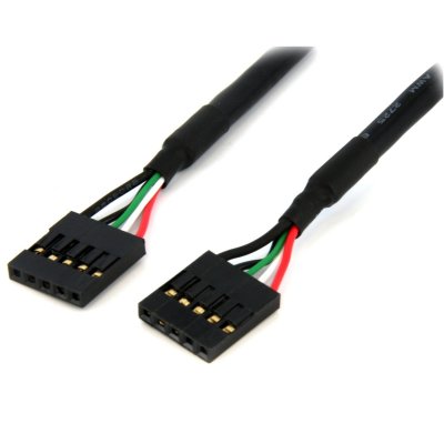
Waiting on parts for my next build - have these items on order for the front cable - StarTech 5pin usb idc header cable (image below)and corsair usb3 upgrade kit
Will use the corsair kit for everything but usb.And the StarTech cable for usb .With a donor apple front panel cable for connector.
I'm hoping this solution will mean no soldering .
Has anyone put together a wiring diagram based on the corsair kit - something like corsair pin 1 to apple pcb pin # ?
Will be using with a new MSI Z77 MA G45 board ( no onboard firewire ) but want to have option of firewire for furture upgrade.
Can I wire firewire header as normal and use a removable jumper ?
 

Attachments

  • usb idc.jpg
    usb idc.jpg
    86.7 KB · Views: 531
@minihack / chaos.. / ellhead ......

Waiting on parts for my next build - have these items on order for the front cable - StarTech 5pin usb idc header cable (image below)and corsair usb3 upgrade kit
Will use the corsair kit for everything but usb.And the StarTech cable for usb .With a donor apple front panel cable for connector.
I'm hoping this solution will mean no soldering .
Has anyone put together a wiring diagram based on the corsair kit - something like corsair pin 1 to apple pcb pin # ?
Will be using with a new MSI Z77 MA G45 board ( no onboard firewire ) but want to have option of firewire for furture upgrade.
Can I wire firewire header as normal and use a removable jumper ?

Word of warning - some people have told me the Firewire pins on the Corsair kit are now on a separate connector and will not now transfer in as easily to the G5 connector block....
 
Word of warning - some people have told me the Firewire pins on the Corsair kit are now on a separate connector and will not now transfer in as easily to the G5 connector block....

bugger that , I thought I'd made life easy for the cable.
haven't received the corsair kit yet , out of stock .
I might look at an alternative instead
 
Status
Not open for further replies.
Back
Top