Just wanted to mention that I have just put together one of the front panel cables using this panel from the Corsair Obsidian (it is one I use in my kits).
The extra bonus feature of using this part is that on the end of the cables that you can't see in this pic (i.e. behind the metal holder) there is a connector which is basically the same type as the G5 front panel connector, so if you use this part it is VERY easy.
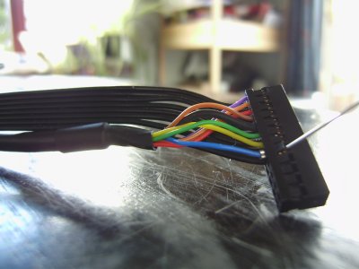
Release each of the end pins from the Corsair connector using a pin to gently push back the plastic of the connector and the little terminated clip slides out. Do the same on the corresponding pin on the G5 connector and then slide in the connection from the Obsidian part. So for the Firewire, the power switch and the power LED there is no need to cut and splice and solder any cables. Unfortunately the USB connections on the Corsair part are not terminated the same way, but it means you just have 4 (or 5) solder connections to do instead of 18.....