Contribute
Register

Ersterhernd's NUCiMac G4

Status
Not open for further replies.
Build Log 2 - NUC Motherboard Mounting

Deciding where and how to seat the NUC system board took a fair bit of thought processing. I ultimately decided that the most functional and aesthetically pleasing location would be in the space held by the previous DVD drive. There is mixed opinion on scrapping DVD drives, but in this build with it's limited workspace, the DVD had to go. In all honesty, I have a USB DVD writer that I only use maybe a couple of times a year. Its compatible with OSX, so why waste nearly a precious 100 cu in of internal space on a redundant piece of hardware that can easily be managed externally by USB?

To affix the the rear I/O in position, I decided to cut out a piece of the original G4 motherboard, preserving four of its mounting holes for fastening to the base of the machine. This allowed the rear I/O to remain firmly seated with little re-engineering. Apple had already done the legwork for me, so why re-invent the wheel? I ground off all the capacitors, memory slots etc with my dremel. I gave the original board a real 'clean shave'. :lol:


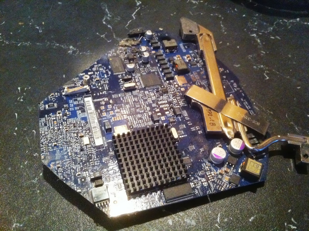
Here's what the original board looks like now, after I painted it black. Several of the rear I/O pieces would later be removed off the board to fit my own. There isn't much left of the original, but what matters is that I preserved four mount holes for a firmly seated fitment.

IMAGE_4AA899FD-7AA2-4B0B-AD0D-76A81CABBBBB.JPG


Here's whats left of the old motherboard. Didn't this used to be round? Rest in Peace.

IMG_3892.JPG


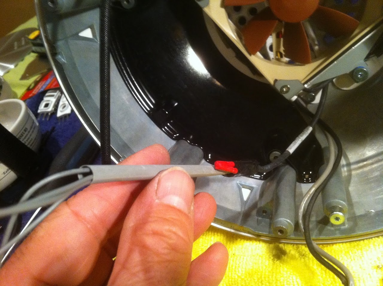
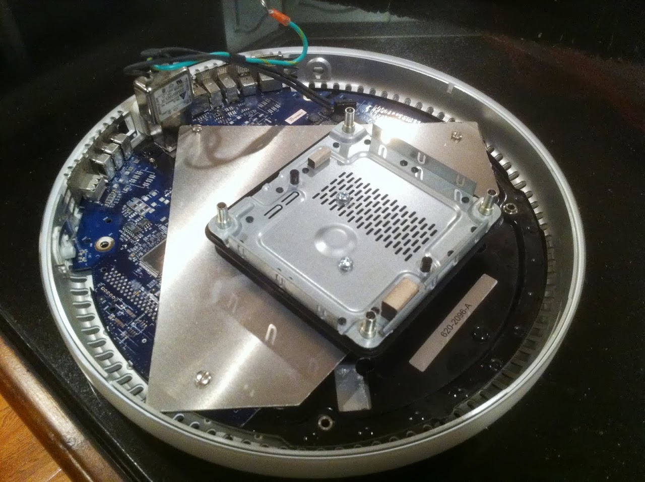
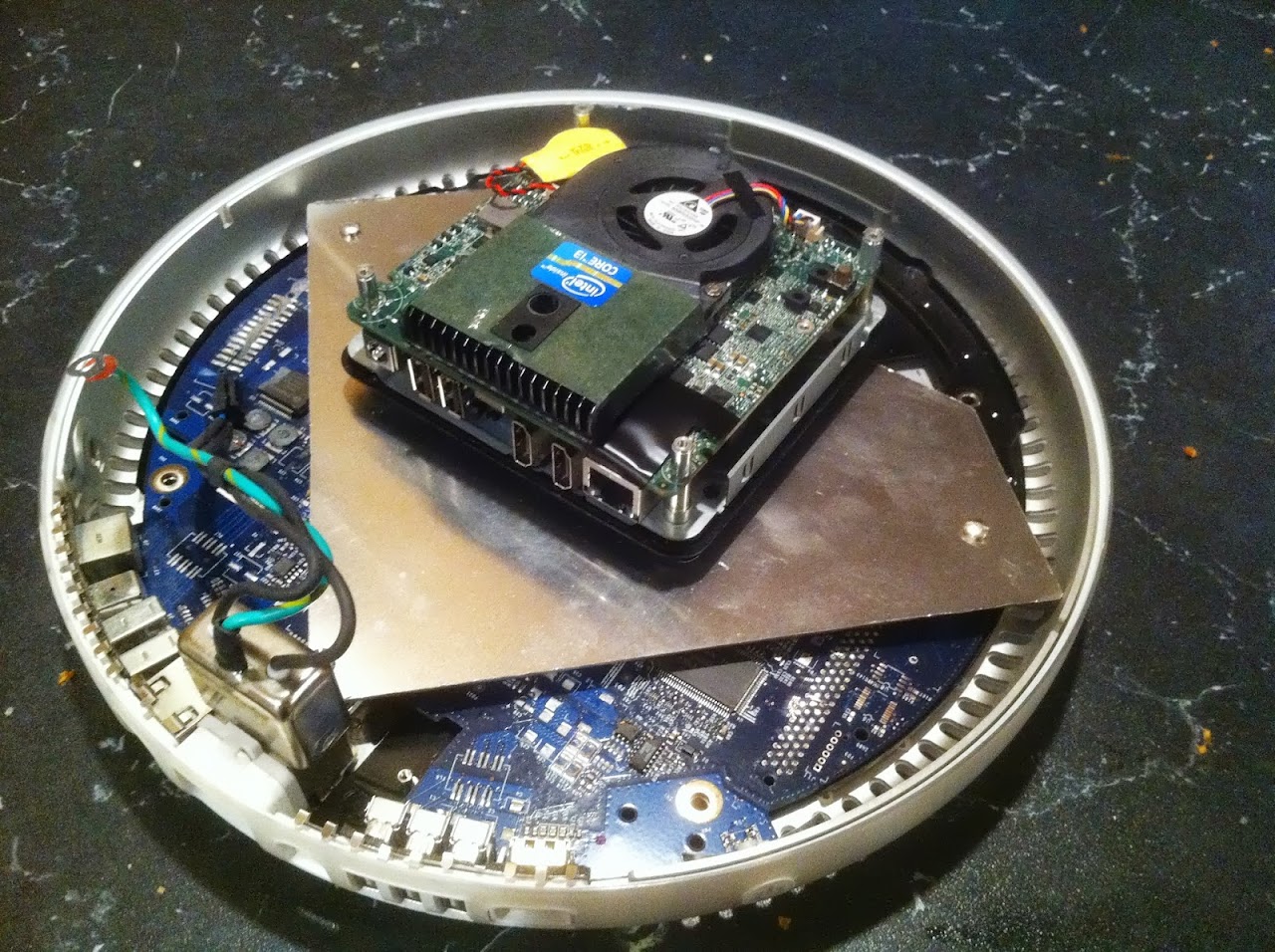
I then cut a plate of aluminum to fit the base. It is drilled to mate up with three of the four motherboard mounting holes. I used UK Electrical Socket Screws (trimmed to correct length) as the thread pattern matches that of the standoffs in the base. These work great in the Apple mods, and I alway keep a package of long ones on hand for re-purposing. They are readily available on eBay. I chose this shape of mounting plate because it leaves access open to the rear I/O, and doesn't impede the critical airflow that will come in through the base vents all around the bottom of the machine, and doesn't collide with the front DVD door. I used the original NUC base to mount the board. It is mounted firmly to the aluminum plate with 2 bolts as shown. (Note that I hadn't painted the G4 motherboard yet in this photo).

IMG_3897.JPG


Rearward view of NUC base mounting

IMG_3898.JPG


To secure the motherboard to the NUC base, access is required from underneath. I drilled four holes in the underside and through the aluminum mounting plate to allow screwdriver access for tightening down the NUC board. It is secured at the top with four original standoffs removed from the NUC case.


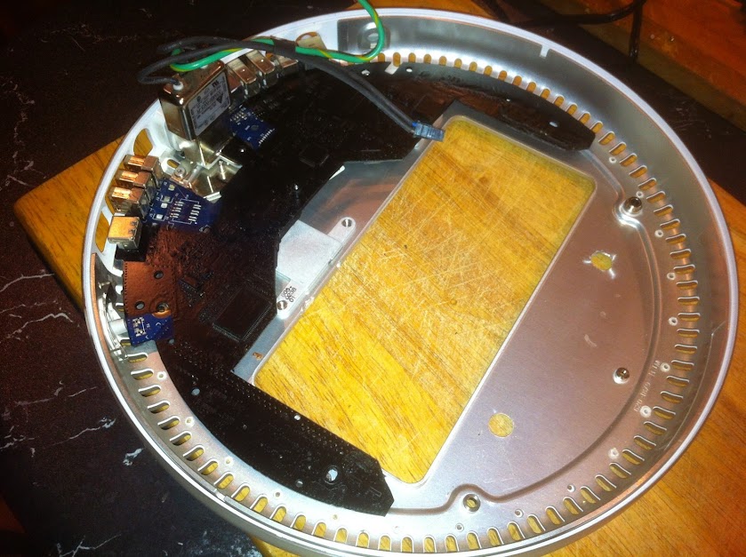
The four screwdriver access holes in the bottom (only 2 are really visible)

t85w.jpg


The NUC firmly secured down using four of its own original standoffs (now on the top) via four screwdriver access holes underneath.

IMG_3901.JPG


I took this photo through the DVD door. It shows the new interior space for the Intel NUC in the original DVD drive location. The new floor sits within about 2mm of the DVD/HDD rack at the bottom, very close measurement paid off. The aluminum floor still had the protective plastic peeling on it, thats why it appears so white. This looks like a great new home for the NUC to live!

IMG_3875.JPG


The base installed in the iMac viewed through the DVD door. The NUC fits perfectly in the previous DVD drive location. There is about 1/8" of clearance between the NUC cooling fan and the G4 Hard Drive rack above it. Wow it was tight, but it all fit in there! :thumbup:

IMG_3907.JPG


Ersterhernd


This may be a silly question, but I'm not very good with electronics yet. If I followed your lead and kept a piece of the motherboard to bolt down the rear IO, how would I ground off everything currently on the board?

Thanks.
 
Hi J, I used a Dremel and a #426 cutting wheel.


Cheers!
 
Only remove what you have to. I'm not sure what you're planning to re-use.

Less is better.


Cheers!
 
I think he is asking where to cut so the back panel connectors are completely disconnected from the on-board circuitry. Did you take a multi-meter and test each pin to see if it was totally isolated after cutting into the motherboard?
 
I think he is asking where to cut so the back panel connectors are completely disconnected from the on-board circuitry. Did you take a multi-meter and test each pin to see if it was totally isolated after cutting into the motherboard?

This was my question, I haven't started my mod yet, I'm just gathering information so I can work over my summer break.
 
Ersterhernd - did you essentially open up the thick plug going from AC outlet to the power brick and put the quick connect 2 port end?

My understanding of the setup includes power coming from the wall & going through the built in iMac converter which connects to the 19V DC power brick. The power brick line splits one with original connector to plug into the NUC, and the other spliced in line powers the PicoPSU.

The PicoPSU powers the fan and the LCD inverter via "homegrown" wiring.

Is that correct?

Build Log 4 - Power Supplies

One of the primary goals of the NUCiMac project is to utilize a single 19V DC Power Brick internally. It will supply both the NUC and also a Wide Input PicoPSU that will send required power to the LCD and 92mm Noctua Case Fan. The NUC comes with a 65W version as part of the retail package, so I will try that first. The big question early on was "Will this be enough power?". I know from my G4 Cube PSU build that the NUC draws around 25W on max load, what I didn't know was how much power the 17" G4 LCD was going to draw. This pressing question had to be answered before I started building the computer.

Unfortunately I do not have my PicoPSU yet, so I grabbed an old ATX PSU and my Kill-A-Watt meter out of the closet to conduct a power test.

Step one was to wire up the inverter in the G4 so I could power up the LCD backlight and test the wattage draw. Following the instructions on the Dremel Junkie's website (thanks again, JBerg!) I had the inverter cable disassembled and wired into the ATX PSU in about an hour. I used temporary wiring and alligator clips for this part for testing purposes only. A permanent and clean solution would be built upon success. The photos of the process are shown below.

EDIT : I have modified the inverter wiring slightly different from The Dremel Junkie's layout. See this post for details.


Inverter Power Draw Test Photos. The first pic is the inverter cable disassembled.

IMG_3887.JPG


There are four wires to be connected, with a 1K Ohm resistor inserted into one of the lines. This photo is the temporary wiring only for testing purposes.

IMG_3914.JPG


Perfect! A fully functional LCD backlight!

IMG_3917.JPG


The power draw from the LCD and 92mm Case Fan -- Under 33 watts. Sorry for this poor quality photo, it reads 32.3 on the gauge.

IMG_3918.JPG


Once I knew for sure that it worked, I built a cleaner final solution for attaching the inverter cable directly to the PicoPSU. Two photos of the completed inverter cable connection are shown below. Connecting it will be as easy as plugging four wires into the Pico.

IMG_3920.JPG


IMG_3919.JPG


The physical mounting of the internal power brick required JB Welding a small piece of aluminum angle bar to the G4 HDD/DVD rack. This created a perfect rubber-lined cradle for the 19V power supply to seat firmly up and out of the way. The green arrow points to the 19V power brick in it's new home.

9k94.jpg


Cabling to the internal Power Brick is wired through the stock G4 plug via the stock G4 2-pin PSU power connector. The earth wire fastens to the case with one screw. Connect/Disconnect takes about 20 seconds.

tst6.jpg


Cabling coming out of the internal 19V power brick goes to the NUC and to the PicoPSU. I'm still waiting for one more male 5.5mm/2.5mm socket plug that will be wired onto this setup for split power to both destinations. The photo below shows the empty taped-off lead waiting for the additional male end.

The Completed Power Loop for a totally internal solution

IMG_3928.JPG


Ersterhernd
 
Yes hinsight, that is correct.


Cheers!
 
Haven't yet read all over, but i had my imac G4 15 ready next to me. the nuc D34010WYK is coming shortly.
but i didn't some reading on intel's materials, found probably more improvements might be for your consideration.
1. the nuc or 2nd gen, accept 12v~24v, there is an internal 2pin connector are available, however, for 1st gen, or DC3217BY, only 19V, but it does come with internal connector, that you may not need to put the power adapter inside it. I had 1st gen ever, but forget if there is that connector.
2.the nuc is coming with vesa mount, any chance to use that as a mounting plate, rather to drill the unit itself?
3. i am trying to buy all useful connectors rather just cut the boards or soldering the wires on the boards, it is more wise, and we can sell the boards for some funds, is that a better idea?
any how, I am still waiting for all my parts' arrival.
 
1. the nuc or 2nd gen, accept 12v~24v, there is an internal 2pin connector are available, however, for 1st gen, or DC3217BY, only 19V, but it does come with internal connector, that you may not need to put the power adapter inside it. I had 1st gen ever, but forget if there is that connector.

I actually did use a 2nd gen NUC in my other G4 17" Build. For the added cost, it was not worth it. There needs to be a patched kernel installed with most updates, too. The original NUC was much easier to get OSX running and updated.

I wouldn't put the power brick anywhere except inside the dome. It was one of the first considerations in the project to figure out a method of using internal power. The finished look of the build in my opinion MUST use only a single external power cord as supplied originally with the iMac G4. Any other external power source was simply not an option for me.

If you have ordered the 34010WYK then you may have a graphics problem, as I don't believe OSX supports Intel HD4400, at least not yet. I may be wrong on that, but if not, you likely will not get full graphics acceleration or other functionality.


2.the nuc is coming with vesa mount, any chance to use that as a mounting plate, rather to drill the unit itself?

There simply isnt room inside the dome to use a Vesa plate, at least not with my builds. Even as is, I only had a couple of mm of clearance.


3. i am trying to buy all useful connectors rather just cut the boards or soldering the wires on the boards, it is more wise, and we can sell the boards for some funds, is that a better idea?
any how, I am still waiting for all my parts' arrival.

I'm not sure exactly what you mean, but selling these computers is simply asking for trouble. The end user must have extensive knowledge of the hardware and software requirements to make one of these work properly. Hackintoshing and Modding are not typically in the common scope of the retail buyer.


Good Luck, but check into that model of NUC before it arrives, as I'm not certain its going to work in OSX.


Cheers!
 
Status
Not open for further replies.
Back
Top