7) Ascent to the Summit: Assembly
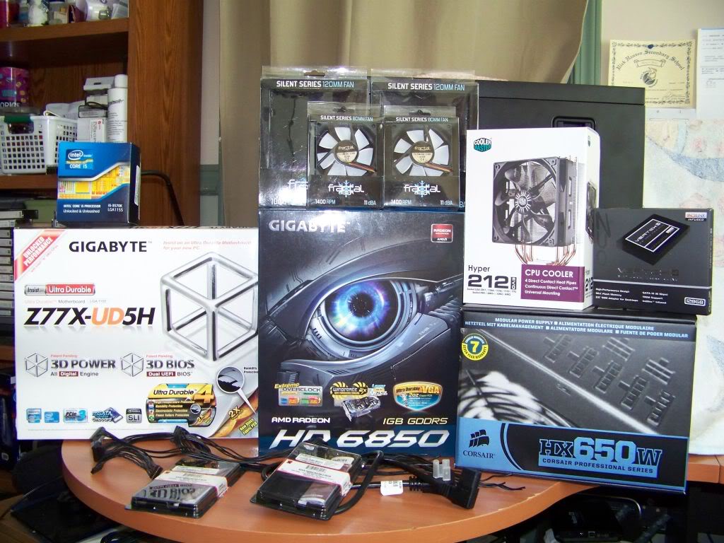
All but one of my parts has arrived. I am still waiting for the EIC power inlet and I cant complete cutting of the G5 back panel without it. I can’t cut with any of the components installed (can’t risk an aluminum shard shorting something out on the motherboard). So I decided I would do a dry run and see how all the parts fit together and sort out some cable management details.
This is almost like Christmas morning. All these parts get to find a new home inside a G5!
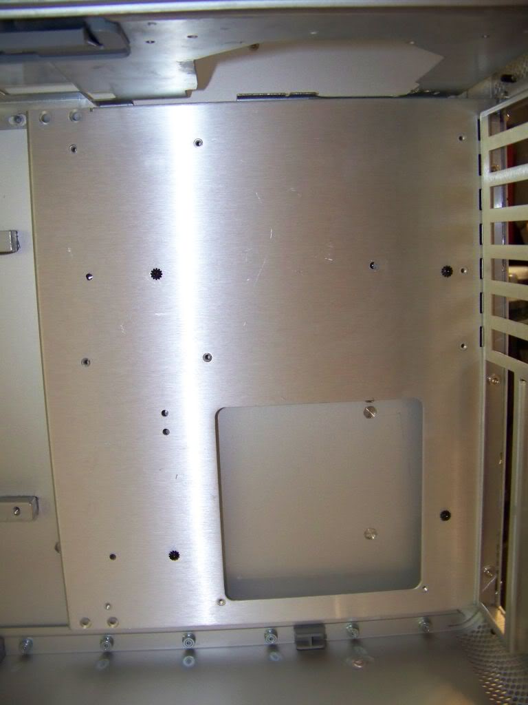
I had read that some of the standoffs in the G5 case were slightly shorter than others. I hadn’t noticed this before, so I decided to take a second look. Sure enough, 4 of the standoffs are indeed slightly longer. I didn’t want to mount a warped tray, thus warping the motherboard and goodness knows what would happen to PCI slot alignment! So I removed the shorter ones and just used the 4 long ones to mount the tray.
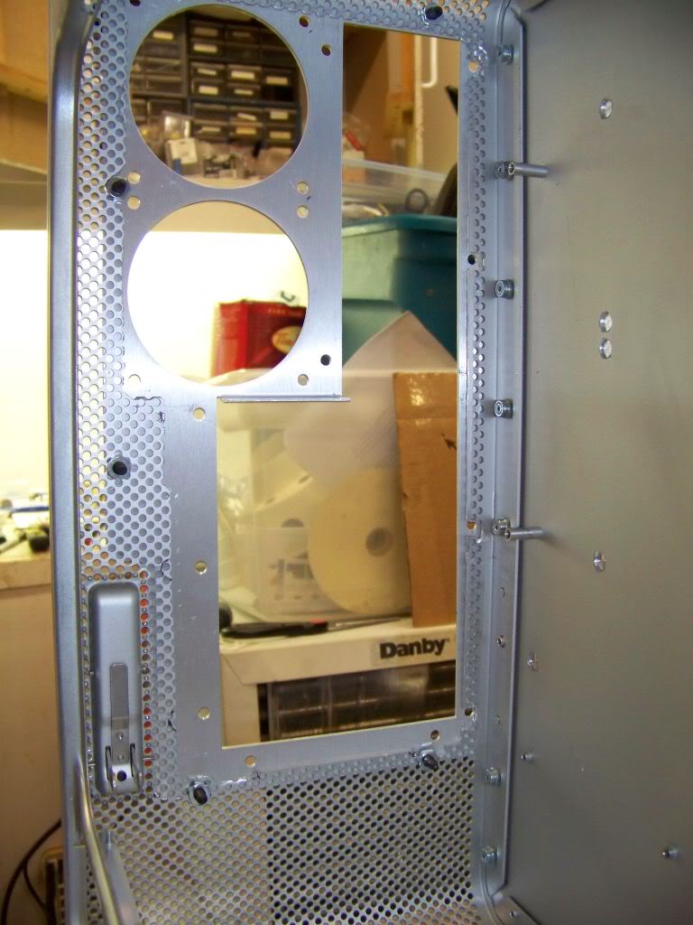
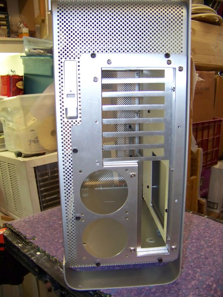
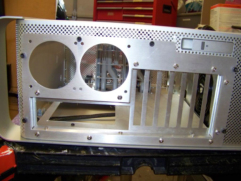
I then test fitted the rear bezel and aligned it with the mounted tray platform. I drilled holes into the case to mount the bezel. I bought some cool bolts to mount it with.
Tray Bezel attached
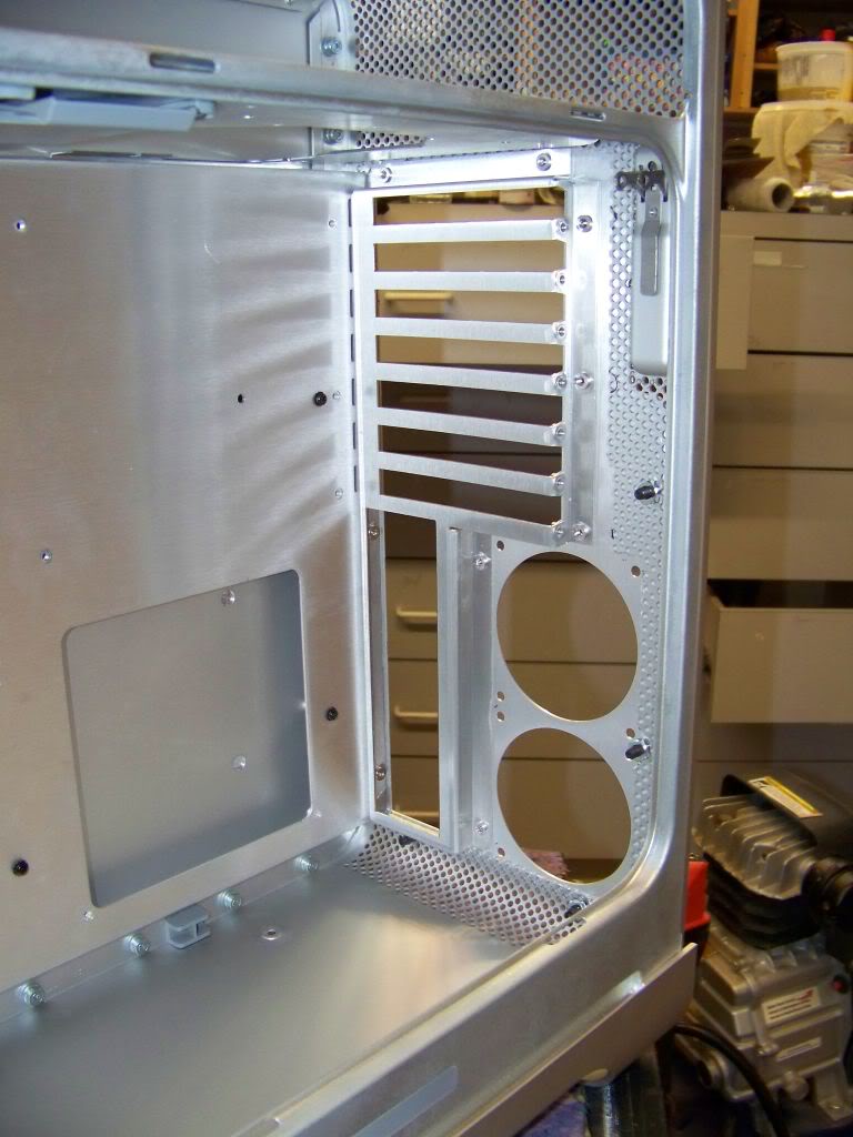
Now that I had all the drilling and cutting/tweaking out of the way, I removed the tray and blew out the case with compressed air to get all the filings etc. out.
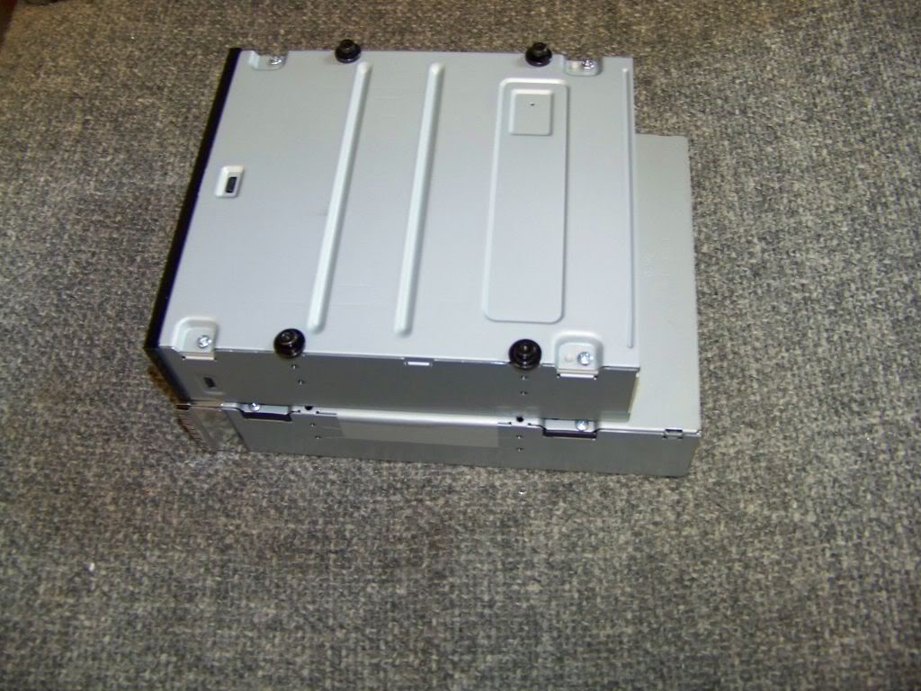
I started by salvaging the mounting screws from the old optical drive and attaching them to the new SATA DVD drive. Hey, the new drive is shorter! This is great because I’m sure I will need the extra space for power cables.
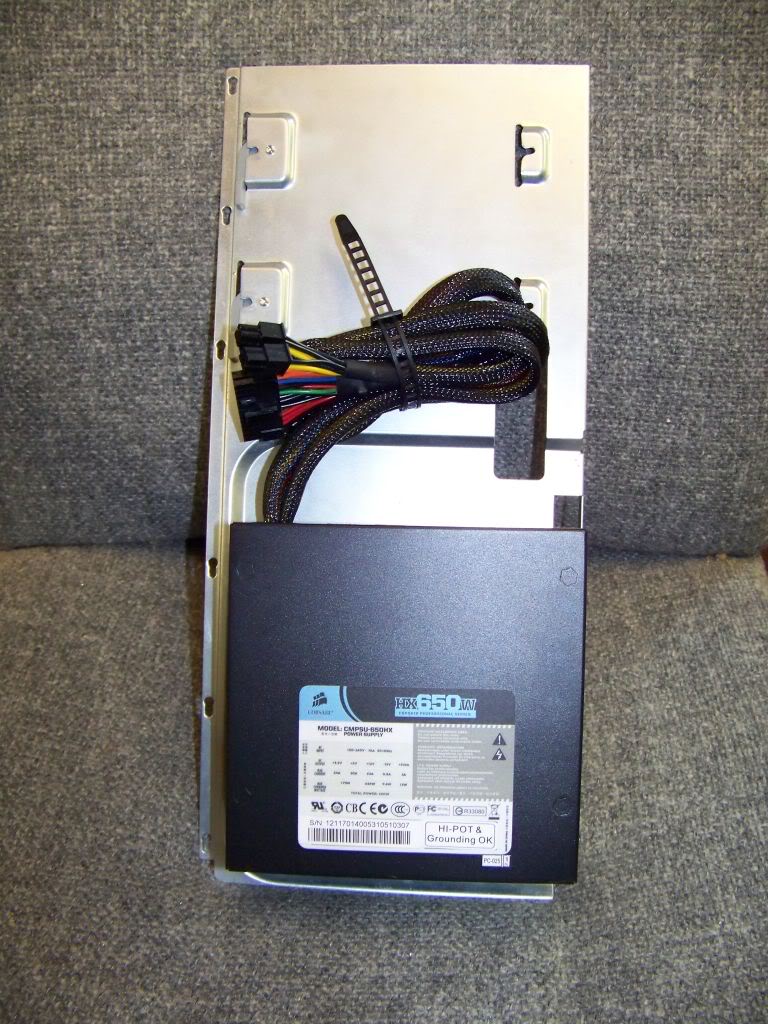
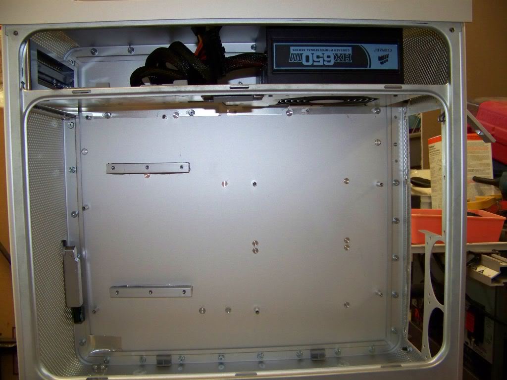
I installed the power supply onto shelf…
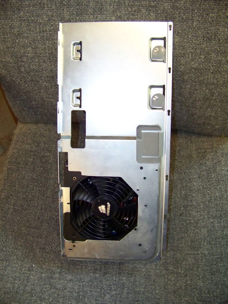
…and installed the shelf into the case. I just temporarily mounted the shelf. I didn’t install the latching mechanism because this all has to come apart so I can cut the opening for the power inlet. I made a mistake here, (I discovered much later) when I tightened the 4 fasteners holding the shelf, I hadn’t slid it all the way to the back. This meant that the optical drive, literally the last piece I installed, would not fit into its mounts!
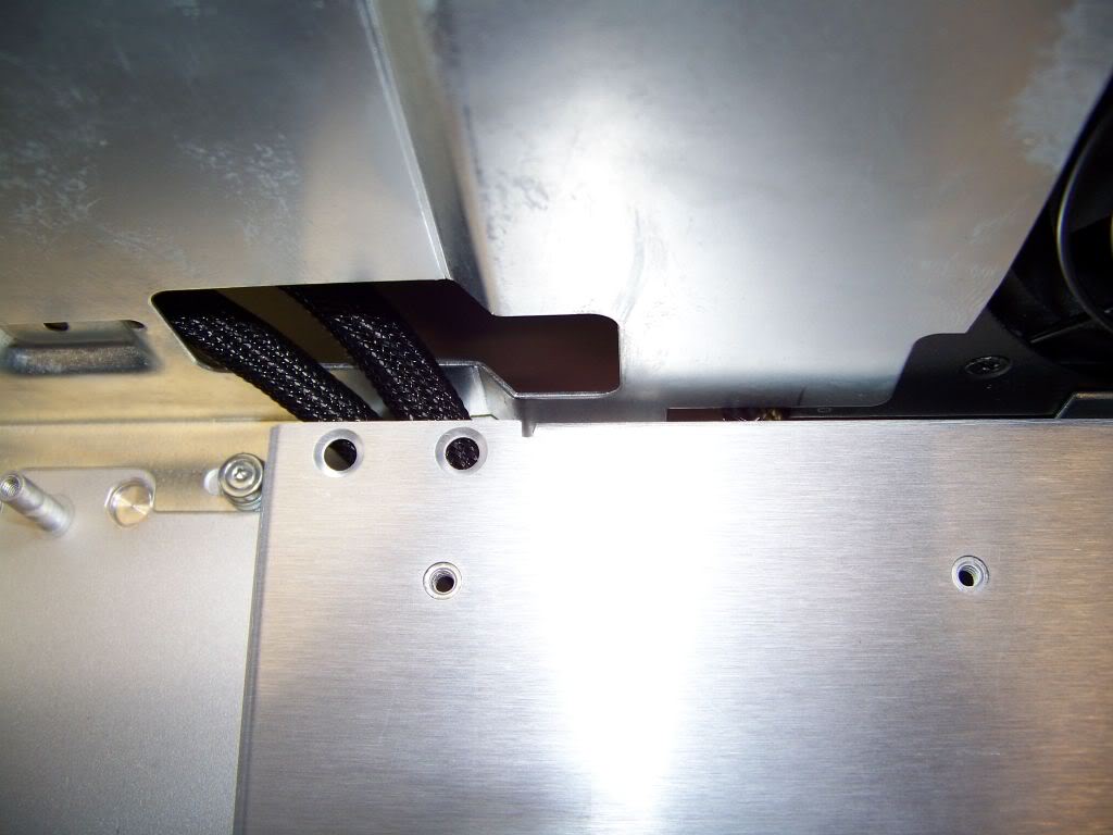
I then re-installed the tray, but only attached it loosely with the two rear-most screws because I want to hide some of the power cabling under the tray. Notice the CPU power cable running under the tray right to the bottom rear corner. I also brought in the drive tray (not yet installed) and planned where its power cables would go…directly under the tray and then up through the hole in the shelf. Nice and neat!
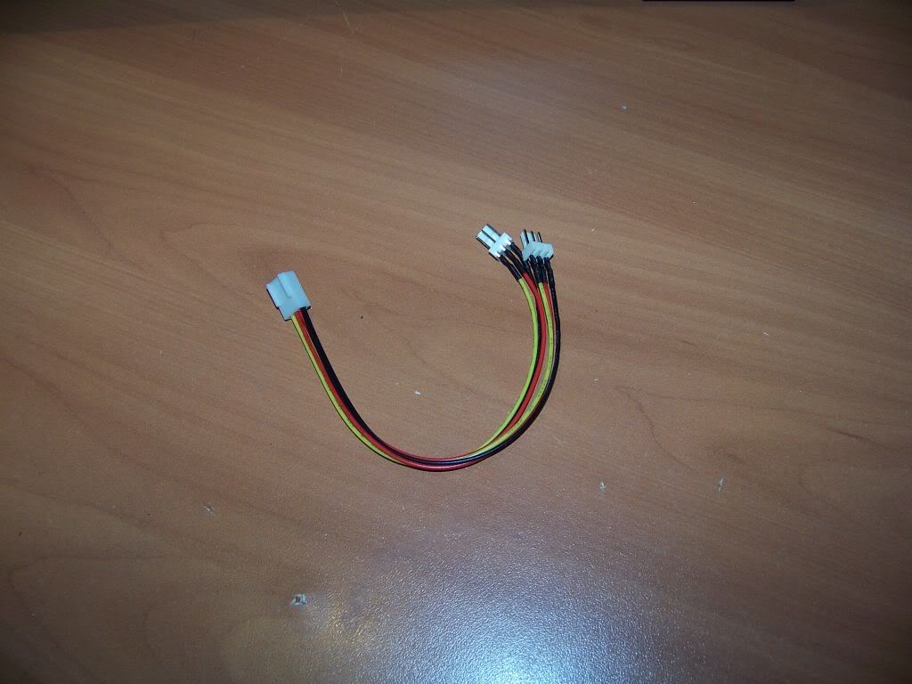
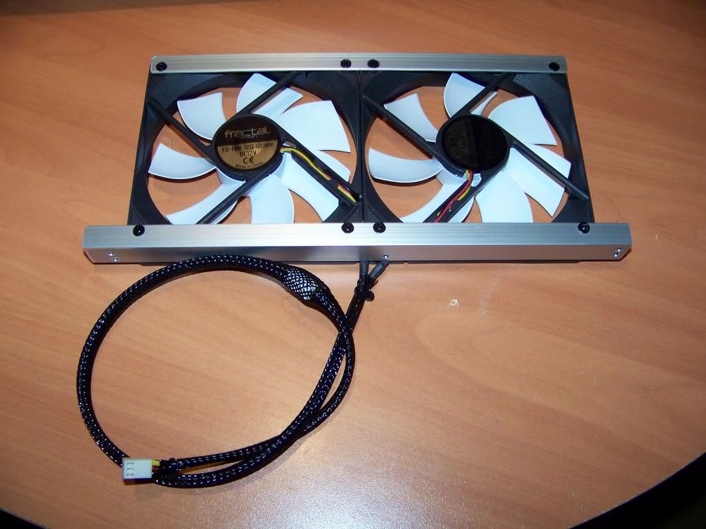
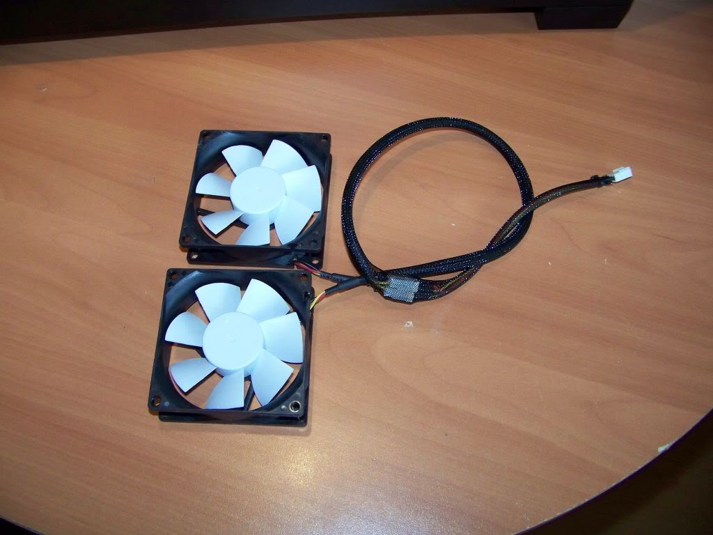
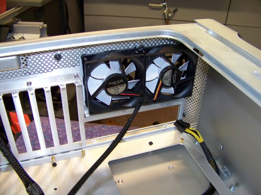
Next to go in will be the rear fans (with their braided power lead)
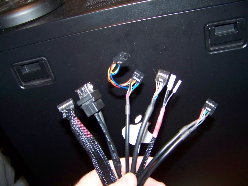
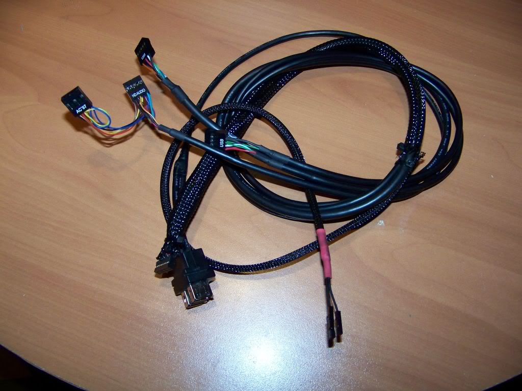
The rear fans are installed now it was time to add the front panel umbilical and figure out where all those wires were going to be hidden.
Here is a shot of the rear fans, from the rear; notice the cool Mountain Mods fan grills. I selected white fan blades for the front and rear fans to specifically highlight these grills.
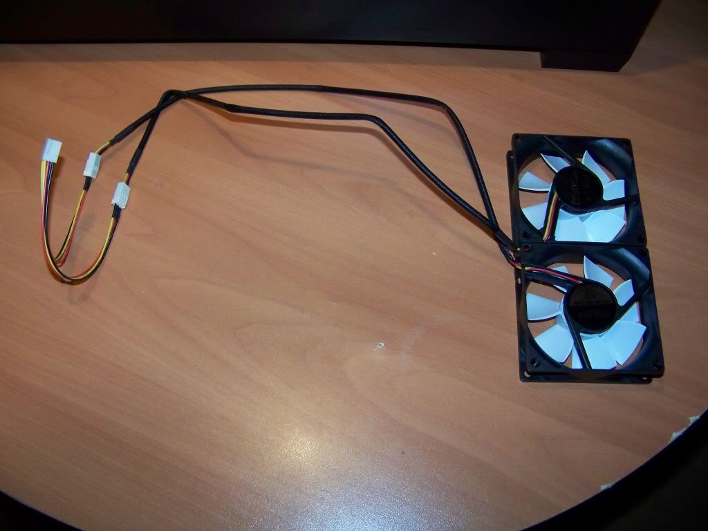
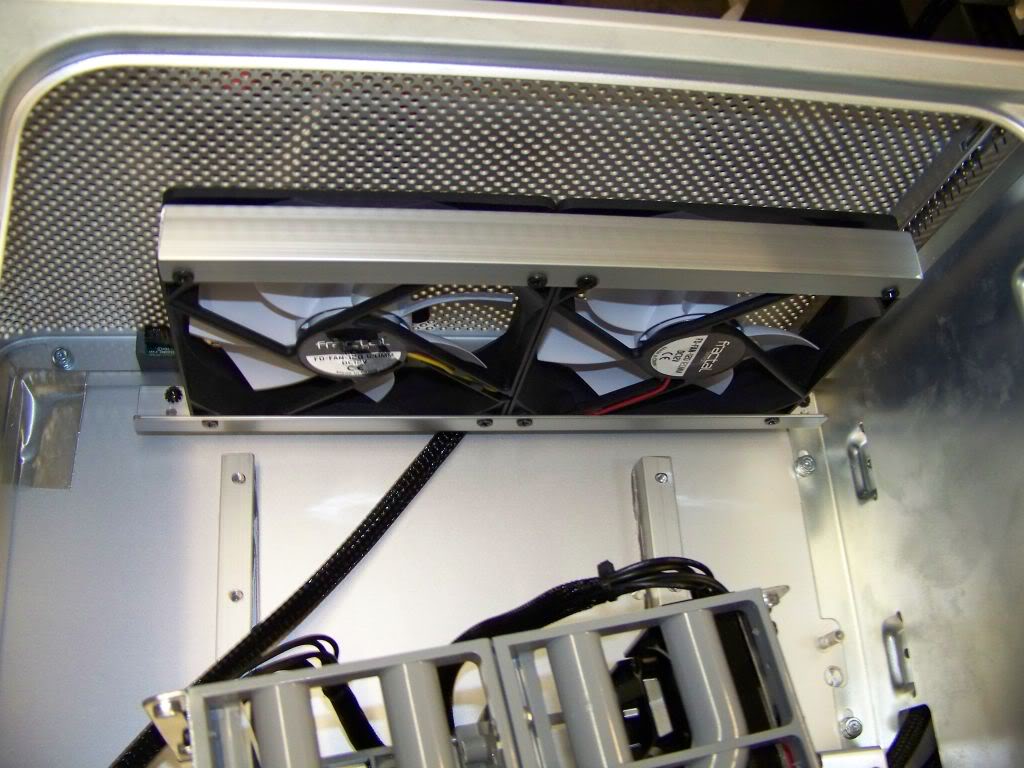
Next came the front fans.
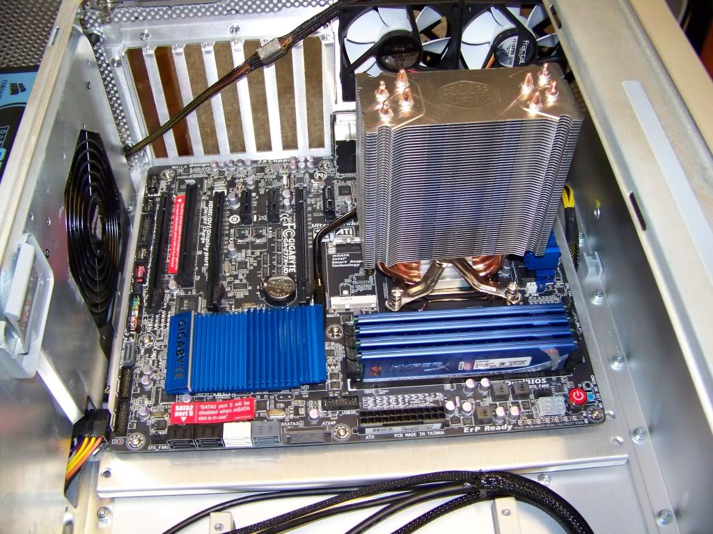
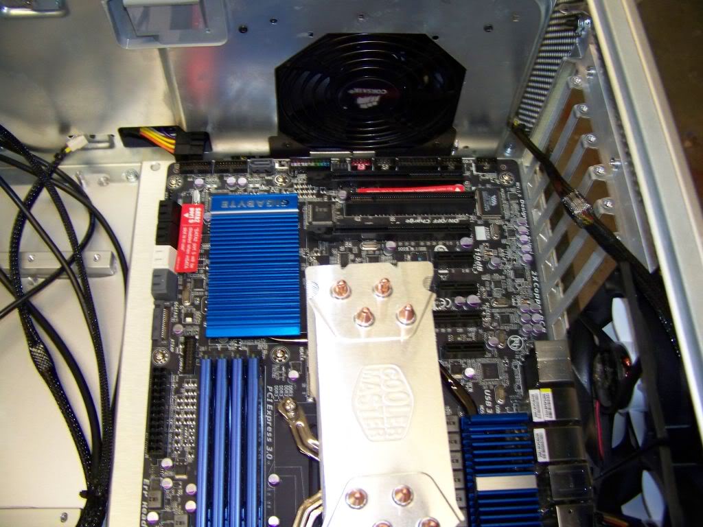
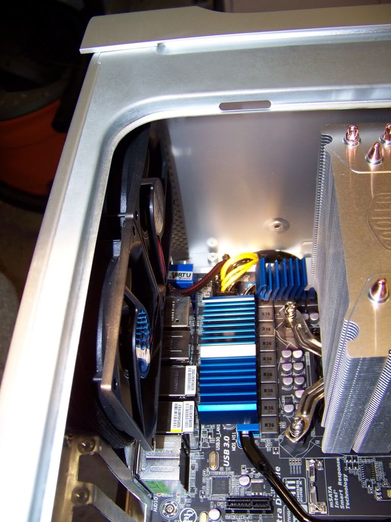
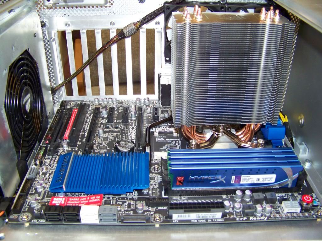
Finally, it was time to install the motherboard so I screwed down the tray and screwed in the brass motherboard supports. Notice that the drive cage is not installed before this step, as I need all the room I can get to mount the board. Also, since the tray cannot be removed, assembled, I mounted the CPU cooler and the memory before installing it into the case. I popped the motherboards port shield into the bezel and then carefully placed the board into position. The cooler barely fit! I might next time just install the base of the cooler and leave the fins and fan until after the board is installed.
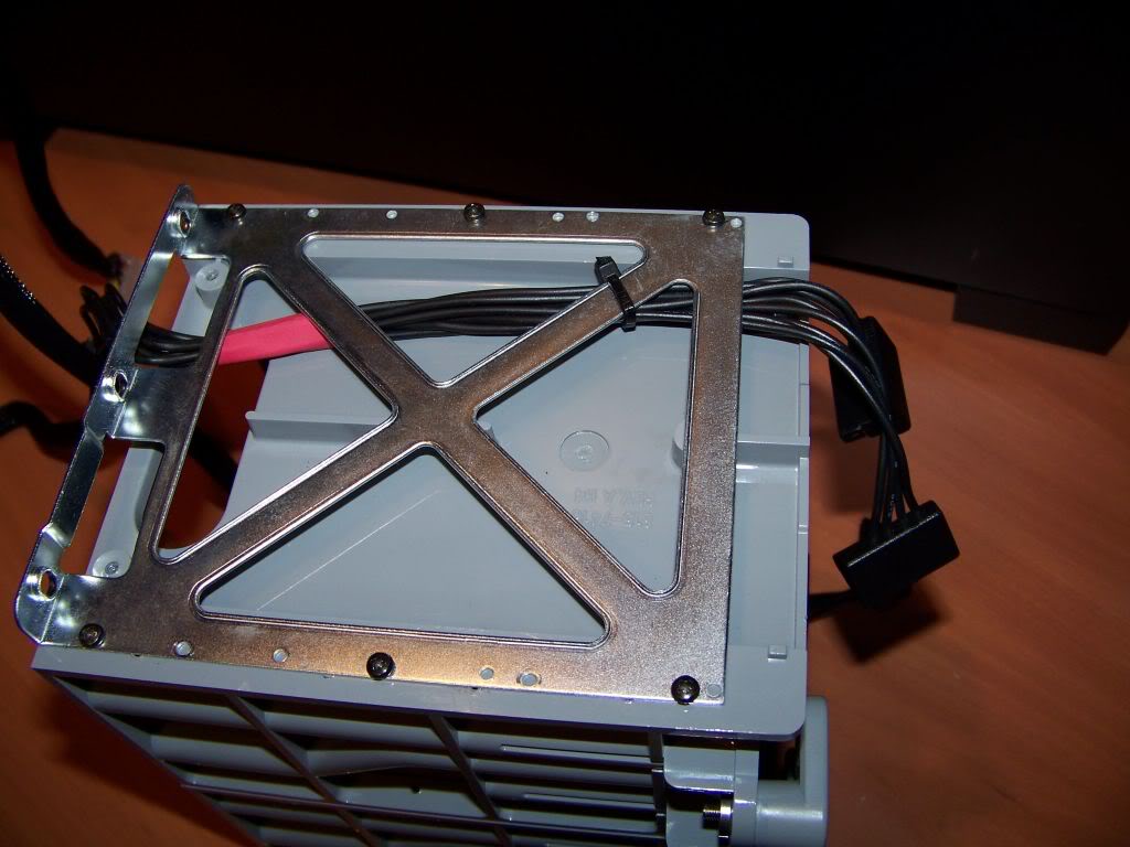
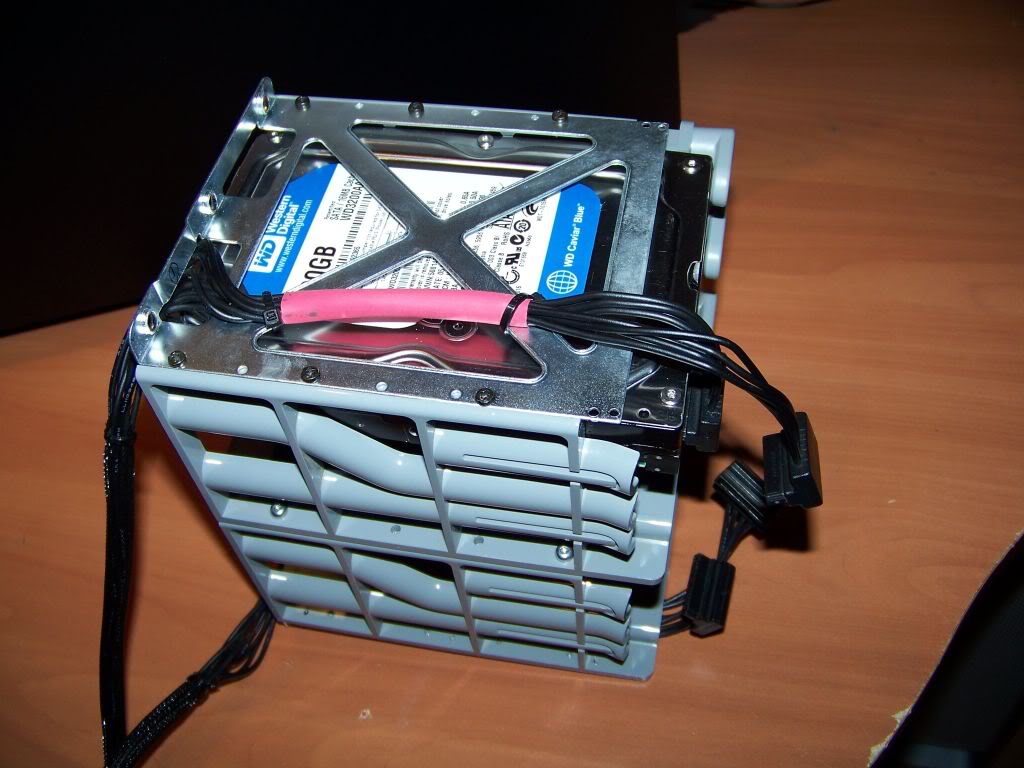
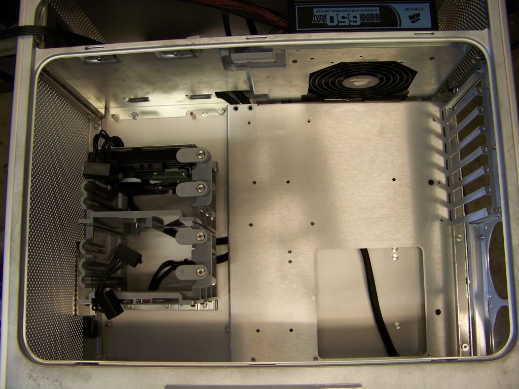
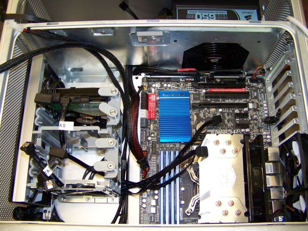
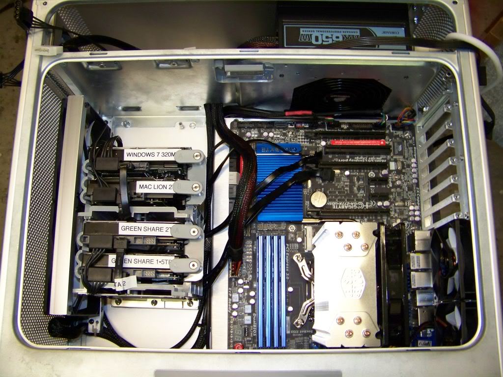
I installed the drive cage next. The mounting bars made this step a breeze. They also left enough space behind the cage to tuck in wires.
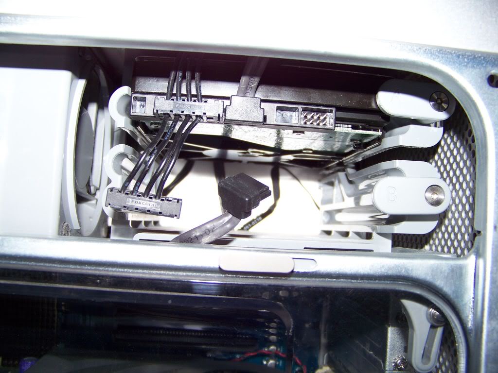
Installing and wiring the drives. Note the SATA cable positions. I am particularly pleased with how this turned out.
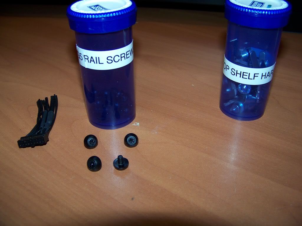
And of course you need a bunch of these rail screws to mount the drives as Apple intended. Final cost? About $3 a screw. They should be gold plated at that price.
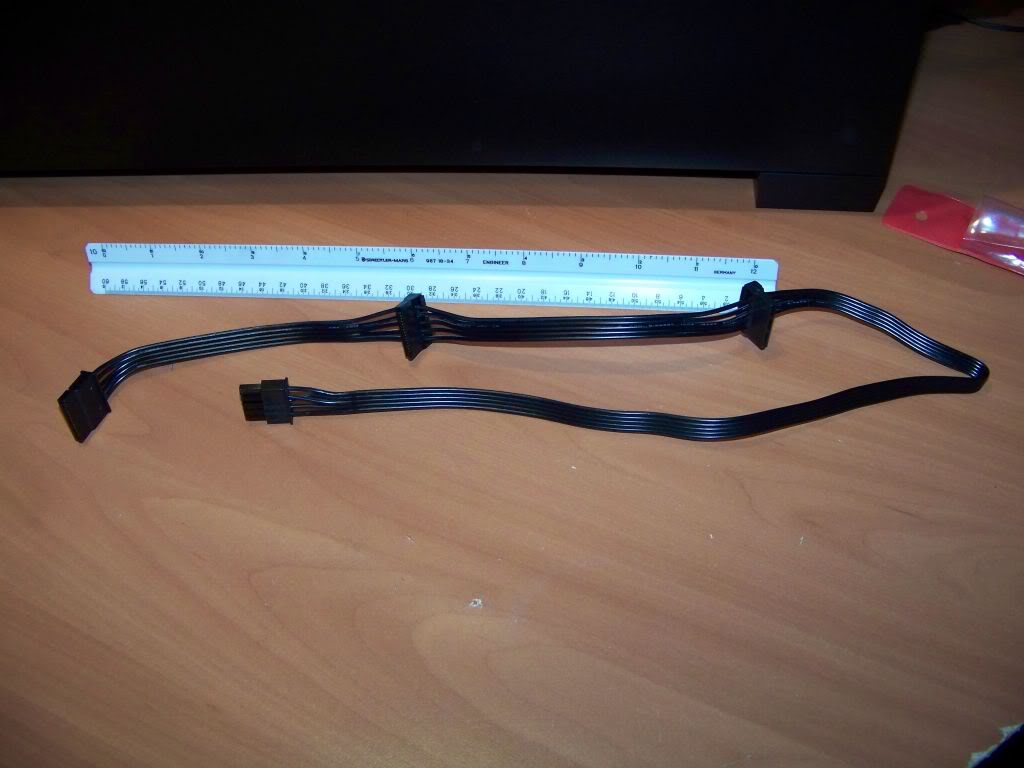
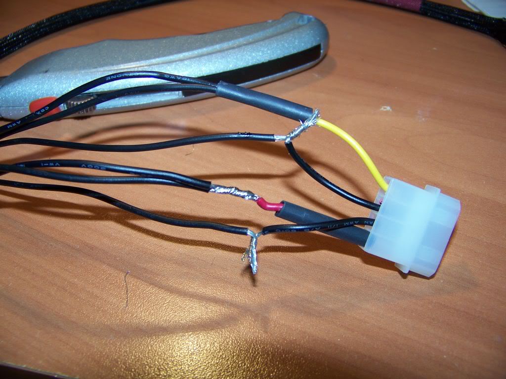
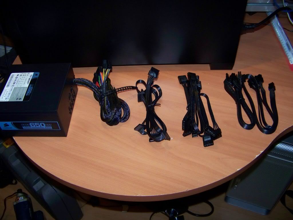
I started to connect up the all the wires to the motherboard; first the CPU power.
Notice the limited space between the case and the top of the cooler…. Yikes!
Here is how the lower section turned out after I managed all the cables. Notice the graphics card has been installed. Remember the extra USB port? Well I just have it coiled up sitting in the bottom of the case for now.
What I like about this setup is that it is nice and clean, and I am still able to add/remove parts without too much wire fiddling. I don’t have to remove panels that are hiding wires, and the wires themselves look nice.
At this point I bunched up all the extra power cables up near the power supply behind the optical drive. I then installed, well tried to install, the optical drive and discovered the mistake I made 5 hours earlier. At this point I’m not too worried because it all has to come apart when that final part arrives. At that time I will come up with a better solution for the power cable mess behind the optical drive.
Time to fire this puppy up!
Front view
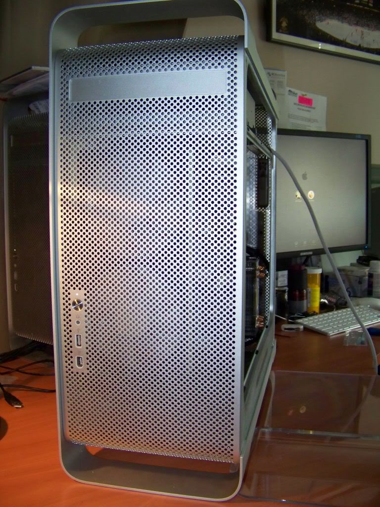
Side view
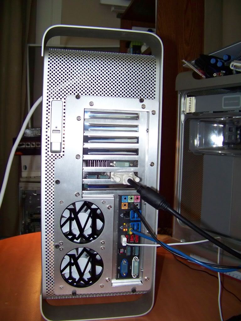
Rear View
And here it is with the plastic air bezel attached. Notice my beautiful Quad G5 in the background. This new Hackintosh will look great sitting next to it everyday!
Stay tuned….This is not the end of the story!

")