Contribute
Register

First Powermac G5 (Late 2005) Project - Design According to Ive

Status
Not open for further replies.
Removable Front CPU Fan Assembly

By now I have probably covered the intent to reuse the removable CPU fan assembly and connectors, trim and mount the fans on the other (right) side of the bracket. I used a hacksaw to trim the overhang from the left hand side of the fan bracket to allow the HDD bay to fit in.

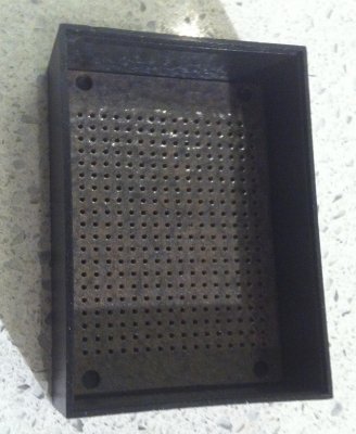
The unmodified bracket
IMG_0913.jpg

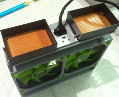
The modified bracket showing where the fans will be placed
IMG_1030.jpg

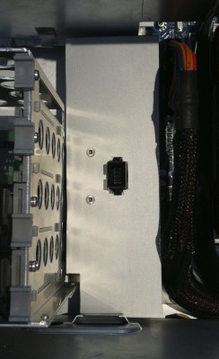
I drilled a hole in the bracket directly under the socket to pass the cables from the socket through. Then I mounted two fans to the right hand side of the frame.
IMG_1035.jpg
attachment.php
IMG_1036.JPG

I purchased 2x "AiMaxx eNVicooler 92mm" case fans. These were the first fans I purchased, they were inexpensive but couldn't get anymore, so settled on the Fractal Design Silent Series for the rest of the build.

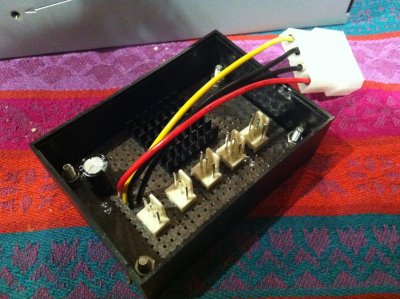
I mounted the new fans using the rubber that came with the fans on the right hand side of the bracket. I cut the connectors off the fan cables and joined the fan cables into the cables coming from the socket.
IMG_1066.jpg

The apple cable and connector came with 6 wires, so used all of these, one for one with my fan cables. To ensure I joined to the correct wire, I used a continuity tester to match to the correct pin on the apple header plug (that connected to the motherboard).

The apple header plug is compatible with normal fan plugs, it just needed to be cut down into two three pin connectors.
IMG_1044.jpg

Once joined the cables were just pushed down into the gap between the fan and the housing. Here is the completed fan assembly.
IMG_1067.jpg
 
Last edited by a moderator:
Mounting the Socket for the CPU Fans

Next in the project was the bracket to hold the socket that the CPU fan assembly plugs into.

The socket was originally supported by a large aluminum bracket that also supported the G5 CPUs. I decided to reuse the existing bracket rather than try to fabricate my own. I cut the aluminum bracket down to size while keeping a couple of screw holes, that i would use to secure it to standoffs I added to my motherboard tray.
IMG_1031.jpg

I used 30mm standoffs which were slightly too short, but the next size up (35mm) seemed too long, so I added some nylon washers to give some more height. It was important to get the standoffs mounted in the right place. I temporarily mounted the socket, bracket, and standoffs to the fan assembly inserted the fan assembly, and market the locations where the standoffs met the motherboard tray. Here (in blue) is where the standoffs ended up.
Moutherboard Locations.jpg

Fan Power Distribution

Underneath the fan assembly there is a void space between the motherboard and the HDD drive bay. This is where I will route all the fan cables to and will be a junction point where all fans will connect to a single PSU molex connector. I choose this location based on its central location to all of the fans and very close to the PSU.

I fabricated a plastic cover (leftover trimmed from fan housing) that would cover up all the cables in this void, including the SATA cables between motherboard and HDD bay. This is mounted to the same standoffs using the same screws, and needed to be cut to allow the fan connector to pass through it. Here are some pictures during construction.

IMG_1038.jpgIMG_1040.jpgIMG_1042.jpgIMG_1043.jpg

Here what it looks like installed, you can see the HDD bay to the left and MB and main ATX power cable to the right.
IMG_1214.jpg
 
I like what you have done with the sata cables.
Might use this idea :) Also like the idea of using the original fan brackets.
Will look into that and see if they fit when i instal the power supply.


I now have my Mountain mod backplate with the 2x80 mm fans.
And might have found a solution for the front-panel.
I scored some NZXT case cables on an nice Dutch website
MB powerlines.jpg
They also have a wide stock of power buttons
http://highflow.nl/modding/power-switches/#8
So if I fail to connect the original one i have a fail safe

Now i need to figure out how to mount the MM backplate to the case.
I might try to use the original cpu plate that sits in the case itself
IMG_1015.jpg
 
I like what you have done with the sata cables. Might use this idea :) Also like the idea of using the original fan brackets. Will look into that and see if they fit when i install the power supply.
If you can use my work as inspiration that's great. You will have create a topic so can see your progress.

And might have found a solution for the front-panel. I scored some NZXT case cables on an nice Dutch website. They also have a wide stock of power buttons http://highflow.nl/modding/power-switches/#8 So if I fail to connect the original one i have a fail safe
Those push-buttons do look good.

Now i need to figure out how to mount the MM backplate to the case. I might try to use the original cpu plate that sits in the case itself
I havent seen the MM motherboard tray, but it should be possible to screw it to the CPU plate, it already has a number of standoffs already on it.
 
Fan Power Distribution Board

I built a power distribution board, that took power from a single molex power connector, and connected it to six fans throughout the case. The distribution board will be hidden below the Fan enclosure.

I choose the hobby enclosure and board mainly based on size, to fit below the fan connector mounts. The second PCB is for future expansion, maybe an apple Chime, but it is not a priority.

There is not much to say about the circuit, it just connects the power from a single molex connector to all the fan sockets, much like a splitter cable does. The main thing is to get the polarities of the connections right. The parts needed were:
  • Small hobby circuit board
  • Hobby enclosure to house the board
  • 5 x 3pin PCB mounted fan header male plugs
  • A molex socket, salvaged from fan.
  • An electrolytic capacitor, size unimportant
The PCB I used had copper tracks, running the length of the board so these were perfect. I added the capacitor to help reduce low frequency noise introduced by the fans. I haven't installed small high frequency capacitors

Before I started soldering components I painted the PCB with some spray paint I had lying around. I secured the pcb to the enclose with countersunk screws and bots, and with double sized tape to the underside of the cover.
 

Attachments

  • IMG_1069.jpg
    IMG_1069.jpg
    996.2 KB · Views: 322
  • IMG_1070.jpg
    IMG_1070.jpg
    784 KB · Views: 285
  • IMG_1141.jpg
    IMG_1141.jpg
    1.1 MB · Views: 323
  • IMG_1144.jpg
    IMG_1144.jpg
    892.4 KB · Views: 380
  • IMG_1145.jpg
    IMG_1145.jpg
    976.7 KB · Views: 356
  • IMG_1214.jpg
    IMG_1214.jpg
    408.4 KB · Views: 359
  • IMG_1068.jpg
    IMG_1068.jpg
    377.4 KB · Views: 303
Status
Not open for further replies.
Back
Top