
- Joined
- May 27, 2012
- Messages
- 759
- Motherboard
- DQ77KB
- CPU
- i7-3770S
- Graphics
- HD4000
- Mac
- Mobile Phone
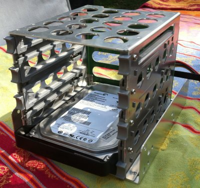
Motherboard Tray
I only had three motherboard standoffs available to use, as four had been left in the case to hold the mid-frame (PCI CPU divider). So had to get new standoffs.
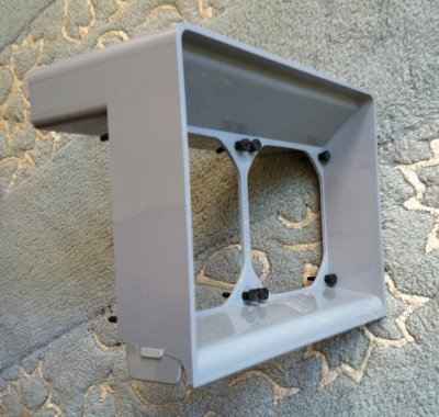
Many projects went with the approach of gluing standoffs directly to the case, and either attaching a MB tray, or MB directly to these standoffs. For some reason I didn't like this approach, but instead decided to emulate the apple design.
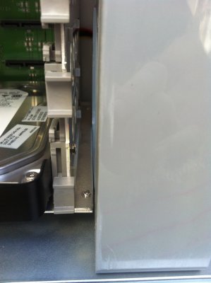
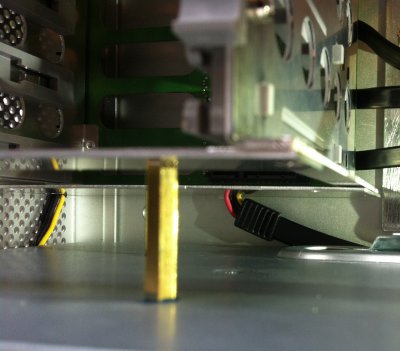
I used a sheet of aluminum, held against case with existing case nuts and screws. These are the ones that held the CPU mounting frame to the case. And mounting the standoffs directly to the aluminum sheet. This approach means, there is no gluing to the actual case, and it gives you the flexibility to replace the tray at any time.
I measured the MB standoffs I had removed they appeared the be 13-14 mm in height, so I purchased 12mm standoffs and an aluminum sheet of 1.5 mm in thickness. The dimensions of the sheet were 34x29cm which easily accommodated a full 30x24cm ATX motherboard. I kept the extra size because it gave me the chance to mount other things to it latter.
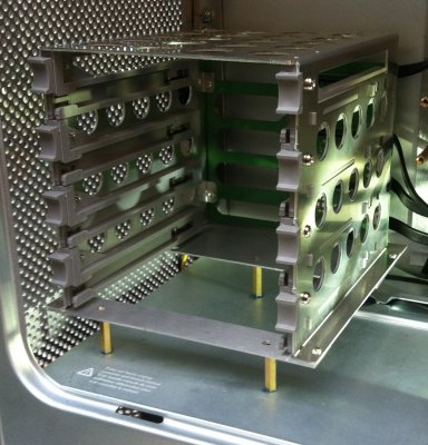
I did have to cut a corner of it out, to have space for the optical drive tray mounting holes. To build the tray basically was in two parts, mounting the aluminum sheet to the case, then mounting the standoffs to the aluminum sheet.
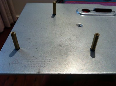
First it involved measuring the case standoffs and drill holds in the aluminum sheet. The existing CPU frame, that was screwed into the mounts, acted as a template for many of the holes. Once all the holes were drilled, the aluminum sheet could be screwed to the frame. Note: many of the holes I drilled had to be widened, because I was not very accurate with a ruler, pen, and hand drill.
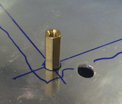
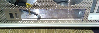
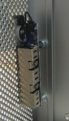
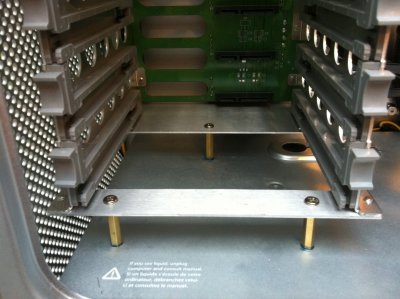
Next was the mounting of the standoffs, this was a very similar process to measure and drill holes. I used countersunk screws from underneath, to hold the standoffs to the tray. I used locktite the help held the standoffs in place and tightened the screws fairly tightly. There are exact specifications for ATX hole placement, so was able to do a better job of alignment.
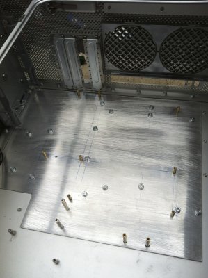
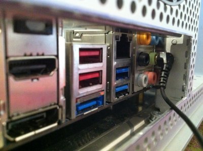
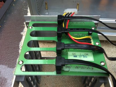
Last I sanded the plate back a little bit (to give it a brushed look), I should have done this before I put in the standoffs , but mostly this wont bee seen anyway. You can see the results below.
I only had three motherboard standoffs available to use, as four had been left in the case to hold the mid-frame (PCI CPU divider). So had to get new standoffs.
Many projects went with the approach of gluing standoffs directly to the case, and either attaching a MB tray, or MB directly to these standoffs. For some reason I didn't like this approach, but instead decided to emulate the apple design.
I used a sheet of aluminum, held against case with existing case nuts and screws. These are the ones that held the CPU mounting frame to the case. And mounting the standoffs directly to the aluminum sheet. This approach means, there is no gluing to the actual case, and it gives you the flexibility to replace the tray at any time.
I measured the MB standoffs I had removed they appeared the be 13-14 mm in height, so I purchased 12mm standoffs and an aluminum sheet of 1.5 mm in thickness. The dimensions of the sheet were 34x29cm which easily accommodated a full 30x24cm ATX motherboard. I kept the extra size because it gave me the chance to mount other things to it latter.
I did have to cut a corner of it out, to have space for the optical drive tray mounting holes. To build the tray basically was in two parts, mounting the aluminum sheet to the case, then mounting the standoffs to the aluminum sheet.
First it involved measuring the case standoffs and drill holds in the aluminum sheet. The existing CPU frame, that was screwed into the mounts, acted as a template for many of the holes. Once all the holes were drilled, the aluminum sheet could be screwed to the frame. Note: many of the holes I drilled had to be widened, because I was not very accurate with a ruler, pen, and hand drill.
Next was the mounting of the standoffs, this was a very similar process to measure and drill holes. I used countersunk screws from underneath, to hold the standoffs to the tray. I used locktite the help held the standoffs in place and tightened the screws fairly tightly. There are exact specifications for ATX hole placement, so was able to do a better job of alignment.
Last I sanded the plate back a little bit (to give it a brushed look), I should have done this before I put in the standoffs
, but mostly this wont bee seen anyway. You can see the results below.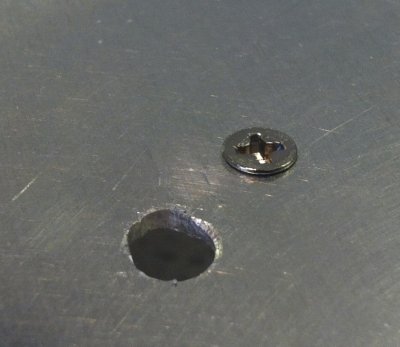


")


