
- Joined
- Aug 16, 2011
- Messages
- 14
- Mac
- Classic Mac
- Mobile Phone
I bought and early 2008 mac pro case. I am putting in a gigabyte p35-ds4 (yes the dremmel and jb weld has been used  : )
: )
Anyway the case I got only has the power button with no front panel logic board. The button does have four wires that go to a very small connector.
Am I going to have to buy the logic board on ebay to make the power button work or is there something else I can do.
I could honestly care less about the front usbs and such. Its going to be in the floor and I have usbs on my monitor but I would love for the power button to work. I am sorry if this is a total noob question but this is my first ever case mod.
Thanks in advance
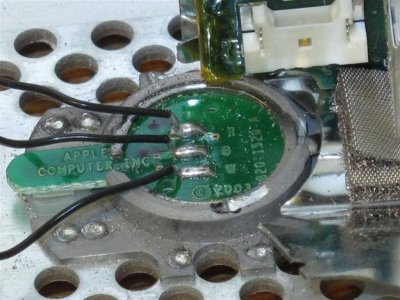
 Should I try to solder it back on or is it a lost cause and get another one on ebay for around $25?
 ")