Contribute
Register

Ersterhernds iMac G5 (iSight 17) Project

Status
Not open for further replies.
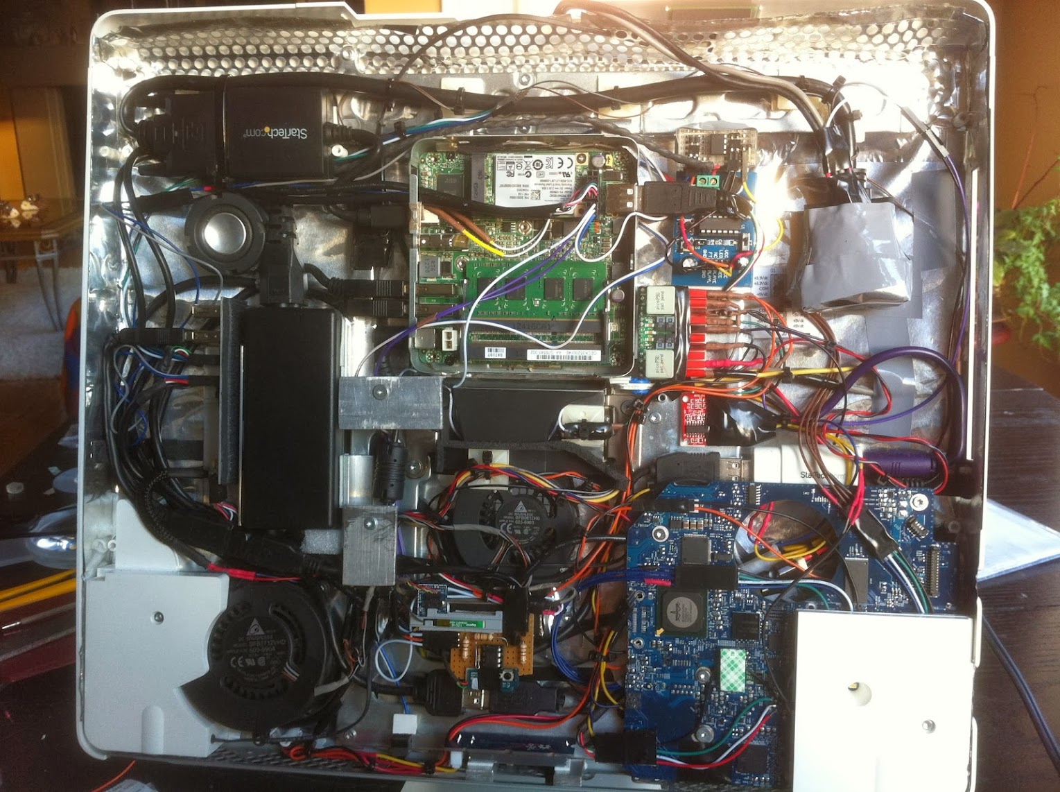
Power Map - Here's the power supply map for the iMac G5 build.


AC Power -

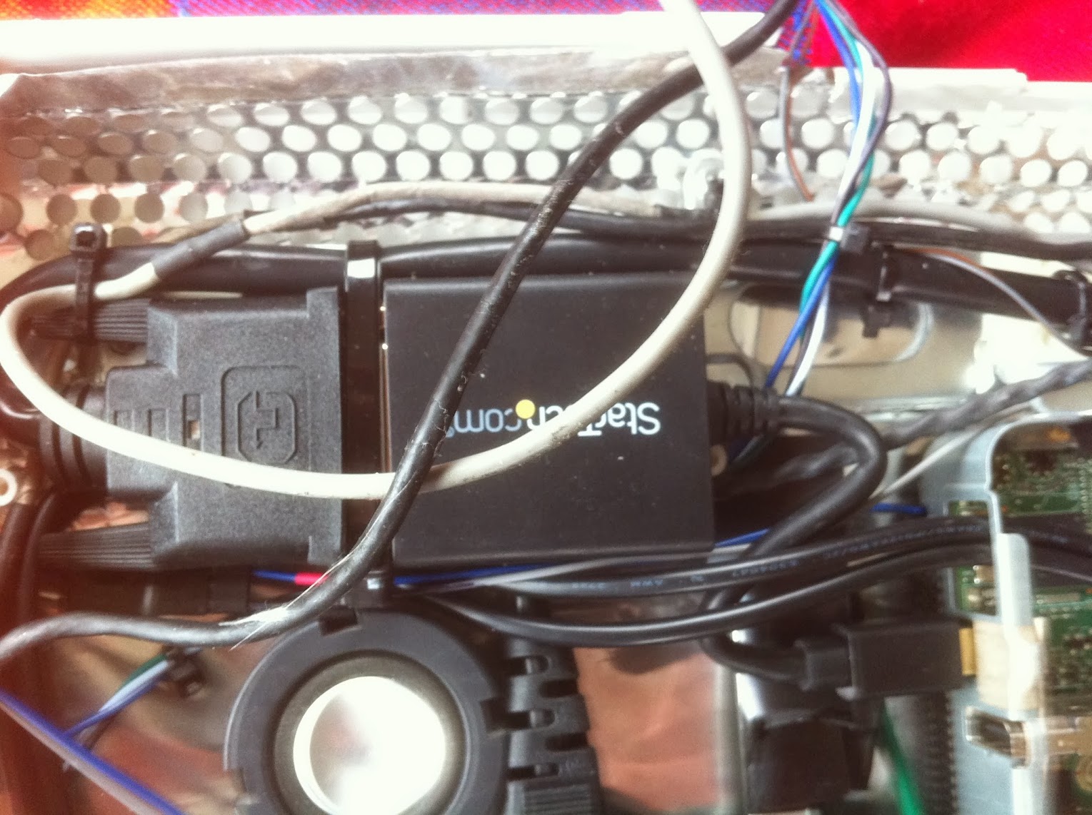
AC power comes into the iMac from the native power cord, through the native AC filter and into the NUC 65W power brick. From there, the 19V DC output line is split into two lines that run to the Intel NUC and PicoPSU.


The DC flow -

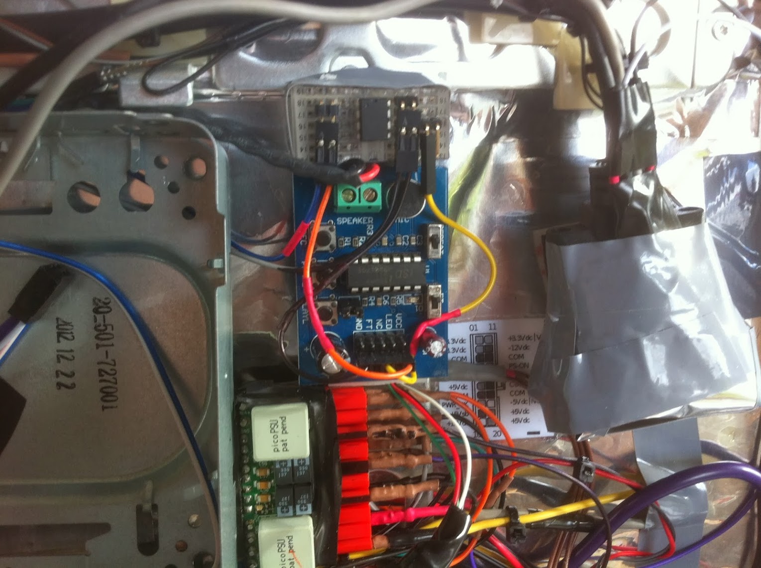
Both the Intel NUC and PicoPSU remain in standby mode when the iMac is plugged in but shut off. The power button on the rear of the iMac is wired to the PWR switch on the NUC front panel header. When the system is turned on by the press of the power button, the NUC starts first and immediately sends 5V from pin 9 of the Front Panel header through a 1KOhm resistor to a BC547B transistor which is connected to PS_ON and GND of the PicoPSU. This activates the power-up of the Pico, which controls all the power in the iMac. At shutdown, the 5V supply from Pin 9 of the NUC Front Panel header stops, subsequently shutting off the PicoPSU and the rest of the iMac.

Total cost was about 25 cents and it works flawlessly for powerup, sleep, rewake and power off. MacTester coached me on how to do this, and its worked great in all four iMac mods I've done.
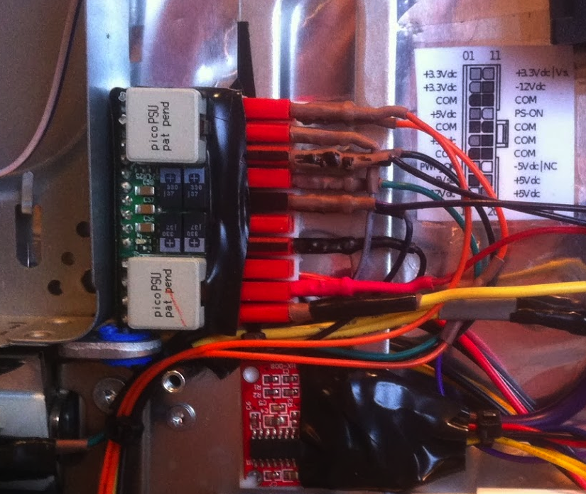

picostartertransistor.jpg


4xu3.png


PicoPSU
PIN - OUTPUT - USAGE
-------------------------
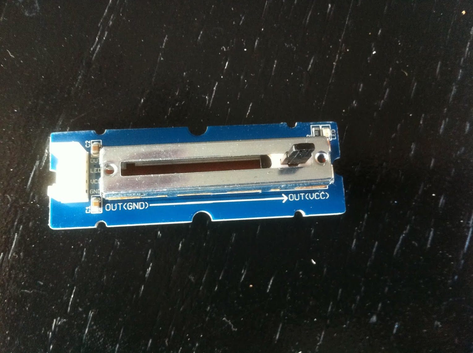
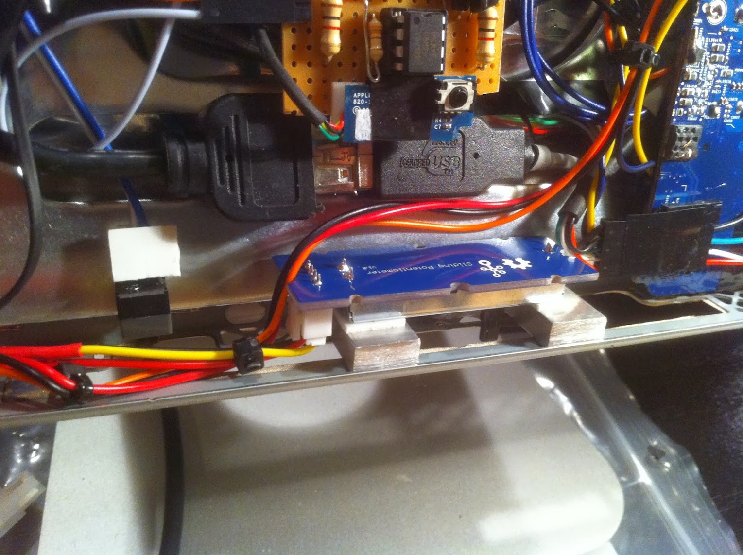
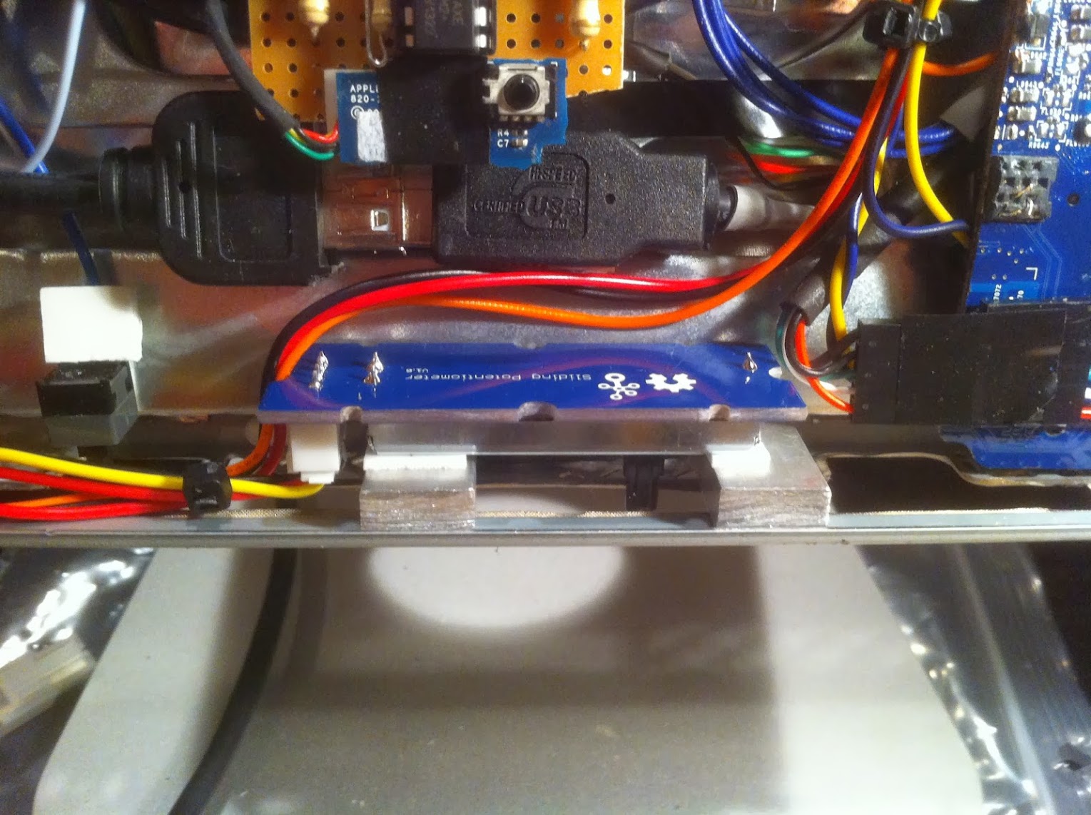
01 - 3.3V - LCD Brightness slider
02 - 3.3V - iMac fan control x 2
03 - GND - floating N/C
04 - 5.0V - floating N/C
05 - GND - LCD
06 - 5.0V - floating N/C
07 - GND - LCD Brightness slider
08 - PWR_OK - floating N/C
09 - 5.0VSB - floating N/C
10 - 12V - iMac Fans x 2

11 - 3.3V - bluetooth & LCD/VEDID
12 - Minus 12V - floating N/C
13 - GND - BC548 power on
14 - PS_ON - BC548 power on
15 - GND - iMac Fan controller x 2
16 - GND - floating N/C
17 - GND - LED controller
18 - Minus 5V - floating N/C
19 - 5.0V - floating N/C
20 - 5.0V - floating N/C

Molex 12V - inverter
Molex GND - inverter
Molex 5V - NZXT USB hub
Molex GND - NZXT USB hub

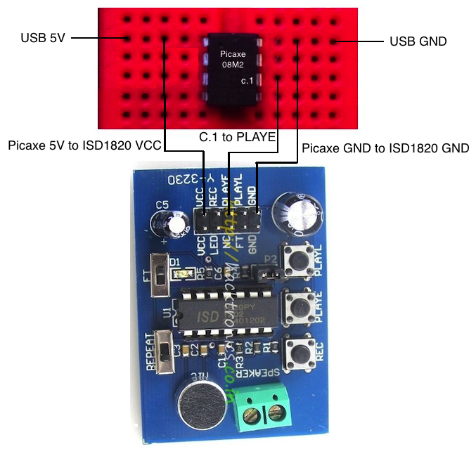
NZXT USB 5V - Arduino ISD1820 & Picaxe Controller for Startup Chime
NZXT USB GND - Arduino ISD1820 & Picaxe Controller for Startup Chime
NZXT USB 5V - PAM8304 Audio Amp
NZXT USB GND - PAM8304 Audio Amp

USB Port 1 - 5V supply to LED Controller

Pin 9 Front Panel Header -
a) 5V to BC548 transistor for PicoPSU startup signal
b) 5V to LED Controller board for system sleep detection


Ersterhernd
 
...

Its coming along nicely, happy with the progress so far. These G5's are actually very nice machines to mod, I was quite surprised as I got into this project. Hoping for good things from this build.

Ersterhernd
Good to hear you are making progress. I share you thoughts about G5, if you can overcome the thinness issues they make excellent machines to mod, the NUC seems to have solved that issue, and is very low power. One of my requirements for a iMac was a 20" inch screen, There are very rare on G4 model, but I am seeing quite a few G5's on eBay.
 
Hi Ersterhernd,

Looks good so far. This DC3217 NUC is very cheap - maybe I will get one and do a "HemiMac Light"? Or maybe a G5??

MacTester
 
Thx Mactester. Just grabbed two of the hdmi connectors. I'd like to at least give this soldering a shot to see if I can do it. Yes the 3217BY is very cheap, but getting harder to buy in Canada. Mines still not arrived.

Another HemiMac, this time a G5?

Sounds great to me!


Ersterhernd
 
Good to hear you are making progress. I share you thoughts about G5, if you can overcome the thinness issues they make excellent machines to mod, the NUC seems to have solved that issue, and is very low power. One of my requirements for a iMac was a 20" inch screen, There are very rare on G4 model, but I am seeing quite a few G5's on eBay.


You're right about the availability of G5's Kiwi. There's several new ones on Craigslist here each day. Some are overpriced but there are bargains too.


Cheers!
 
Build Log 10 -- LCD Brightness Control

In previous iMac projects, I chose (with MacTester's assistance) the Picaxe microcontroller and touch-sensor actuated brightness control for the LCD. In this build, I wanted something simple, effective and clean, yet not complicated to implement or use. The inverter in this iMac G5 has it's brightness controlled by a single wire, it turns the backlights on above 0.7V and can adjust the LCD brightness up to it's maximum at 3.3V. Below 0.7V the backlights turn right off, but fortunately, they will turn back on immediately after the voltage rises up above 0.7 again. There is no other control wire that is required. Basic, simple functionality. I like it. :thumbup:

I decided to search around for a sliding style of potentiometer that the user could easily access to adjust the LCD brightness by simply applying a fingertip adjustment to the left or right. I found what turned out to be the perfect part (if such a thing exists) for this application. Its called the Grove Slide Potentiometer made by a Company called Seeed Studio. (Three 'E's is correct). The link to this inexpensive product is here.

It arrived today and I was pleased at how smooth it feels to adjust. A slight resistance to the fingertip can be felt when moving it over the 30mm of available adjustment travel. It adjusts between 0.8V (left) and 3.3V (right) in my build, so even at the dimmest setting, the LCD will not go completely black. One output wire from the slider carries the inverter reference voltage up a single inverter wire. Very simple. I did a quick test of the slider connected to the iMac LCD and it worked flawlessly.


The Grove Slide Potentiometer (sorry the photos are a little over-exposed)

IMG_4849.JPG


IMG_4848.JPG


The slider will allow fingertip adjustment on the bottom of the iMac, using what used to be the Memory Slot. Only a couple of millimeters of the adjustment knob poke out the bottom, not even visually noticable, but enough to feel and adjust with the fingertip. I used small aluminum blocks for the height adjustment of the slider, and positioned them as left and right 'Stops' so as not to allow the slider to go below 0.8V and keep the LCD backlights on.


The installed Grove Slide Potentiometer with left and right 'Stop' blocks for a range of 0.8V to 3.3V max.

IMG_4850.JPG


IMG_4852.JPG


This photo shows the adjustment knob set to maximum brightness

IMG_4853.JPG


Bottom View of adjustment knob in iMac memory slot, hidden out of sight with easy fingertip accessibility.

IMG_4851.JPG


This method of LCD brightness control may not be as elegant as some, but for this application should work very well with the iMac G5 inverter. Total cost including wires was under 10 dollars; I like that, too. Installation took about an hour to complete.


Ersterhernd
 
Build Log 11 -- Apple Startup Chime

I hadn't previously added this feature to any of my other mods, but really wanted it implemented into this iMac G5. I'd read about different ways to do it, but wanted the key feature of only the 'startup' playback of the chime, maintaining silence upon a sleep/rewake event or press of the power button to cause the machine to do either.

Here's what I decided; it was turned out to be a simple yet effective solution to accomplish my goal.

1. Record the Apple Chime to the ISD1820 by holding it directly up to my iPad speaker. I've attached the small .mp3 to this post if anyone wants it.

2. Use USB 5V and GND to power the circuit. On the NUC DC3217BY, the USB stays fully powered during sleep, which was perfect for this application.

3. Use an Arduino ISD1820 sound recording board to contain the Mac Chime audio clip.

4. Use a Picaxe Microcontroller to send a 'high' signal to the ISD1820, only at startup.


Essentially, here's how it works...

1. Upon system startup, the Picaxe microcontroller gets a 5V supply from USB power.

2. The Arduino ISD1820 board starts at the same time from the same power source.

3. After a second or two that the Picaxe chip takes to boot, it sends one solitary 'high' signal from pin C.1 to the Arduino ISD1820 'PLAYE' pin. The Picaxe pin C.1 is then reset to 'low'.

4. The ISD1820 plays the recorded Mac Chime only once. The repeat switch is set to 'off'.

5. Due to the fact the the USB 5V supply never shuts off until system power-off (stays on during sleep), the Mac Chime has no way to 'replay' itself until the next full power cycle off. Reboots, Sleep and Power Button activity have no effect on the chime.


Mac Startup Chime Circuit

ChimeCircuit.jpg


Photos of my installed circuit boards and speaker (taken from an iMac G4).

IMG_4858.JPG


IMG_4859.JPG


The Mac Chime works flawlessly, it sounds about 2 seconds after the native power button is pressed on the rear of the iMac G5.


Ersterhernd
 

Attachments

  • MacStartUp.mp3
    40 KB · Views: 397
Hi Ersterhernd
Good progress. How did you record the chime to the ISD1820? With the integrated microphone? Is the sound quality acceptable?

Did your thunderbolt NUC already arrive? I'm considering, if I should buy one and do a 2nd iMac...

MacTester
 
Build Log 12 -- iMac G5 LCD Connection

The success or failure of any iMac project really lies in the integrity of the connection from the new video port (HDMI, mDP or the like) to the old LCD, which relies on older TMDS technology for its signal. This project was no different, but presented even a further challenge due to the proprietary connector that Apple used to connect to the G5 logic board. (See this link for the details that I previously discussed).

I started this task in the build by ordering an iMac G4 17' neck. This complete part contains the two necessary video cables required for my G5, they can't be purchased separately as they form part of the original Apple part number 661-2825 which is the entire neck assembly. It cost me (including shipping) about 50 dollars from PowerbookMedic. I'll put a plug in for this Company, they are excellent. They have stock of many obscure Apple parts, are reasonably priced and ship quickly.

When the neck arrived, I spent about an hour figuring out how to dismantle it and get the LCD cables out in their naked form. I must say, the iMac G4 neck is an amazing piece of engineering. I felt almost guilty destroying it. Nonetheless, the two LCD cables (black and grey) were in perfect condition at the end of the process. I stripped the 17 hairlike wires out of the Apple logic board connector, too.


The stripped out wires from the iMac G4 neck

IMG_3934.JPG


At this point, the process became a simple repeat of LCD wiring in my iMac G4 builds. The pinout of the LG LM171W02(TT)(A1) LCD panel allowed a carbon-copy process as in previous iMac G4 panels. Note that I did two minor adjustments from previously to accomodate the 3.3V VEDID requirement of this LCD panel.

1. Wired the VEDID (pink wire in the iMac G4 grey cable) direct to 3.3V supply from the PicoPSU
2. Connected the DVI VEDID pin 14 directly to DVI HOT PLUG DETECT pin 16 via 1KOhm resistor


The Pinout of the LG LM171W02(TT)(A1) LCD Panel (taken direct from the Spec Sheet)

screenshot_129.png


screenshot_141.png


This is a rather crude diagram of the completed TMDS to DVI wiring before I wrapped it all up with EMI shielding. It shows exactly which wires went where, as per the chart above.

VideoWiringDiagram.jpg


The finished product looks like this. I re-used some of the excess EMI shielding material that I got from the iMac G5. It's wrapped around the TMDS wires to protect them from electromagnetic interference.

TMDStoDVIpic.jpg


The 30-pin TMDS connection to the rear of the LCD panel looks like this. I squeezed the EMI shield tape very thin so the wires fit beautifully tucked in behind the LCD panel. I used clear tape to secure it in place.

IMG_4884.JPG


Here is the MiniDisplayport to DVI adaptor plugged into the NUC DC3217BY.

EDIT: MiniDisplayport has been replaced by an HDMI to DVI converter. See this link for details.

IMG_4894.JPG


The completed wiring of the LCD connection runs across the top few inches of the iMac G5. The complete path of the video signals is as follows :

NUC Thunderbolt Port ---> MiniDisplayport/DVI adapter ---> 18" DVI cable ---> TMDS converter ---> iMac G4 LCD cables ---> iMac G5 LCD Panel

EDIT: The NUC HDMI port is now used, not the NUC Thunderbolt port. See this link.

Complete view of the iMac G5 internals before testing the first boot. The video signaling hardware is such a low profile thickness that the LCD panel still just barely fits over top of the entire assembly.

IMG_4863.JPG


One advantage of the iMac G4 LCD cables is that they are about 2 feet long. This give me plenty of length to place the LCD panel away from the iMac G5 (for testing purposes) whilst still allowing me to work on the system with full access to the internals normally tucked behind the LCD panel. My first test power-up of the iMac G5 with LCD connected worked great. I got the BIOS screen right away.

IMG_4867.JPG


Its always a tense moment at the first press of the power button, but this time all went well and I got a working system. So far so good! :thumbup:


Ersterhernd
 
Hi Ersterhernd
Good progress. How did you record the chime to the ISD1820? With the integrated microphone? Is the sound quality acceptable?

Did your thunderbolt NUC already arrive? I'm considering, if I should buy one and do a 2nd iMac...

MacTester

Hi MacTester, yes my NUC did arrive. Best 190 dollars I ever spent. Its terrific, took OSX like a champ. No Ethernet port, but I didn't need it anyway. I think you'd be impressed for the little they cost now.

For the chime, I downloaded an m4a copy to my iPad and held the ISD1820 directly up to the speakers. It took a couple of tries but worked well. Not digital quality, but sounds actually quite authentic, certainly good enough for emulating the original iMac.


Cheers!
 
Status
Not open for further replies.
Back
Top