
- Joined
- Feb 21, 2013
- Messages
- 281
- Motherboard
- Gigabyte GA-B560M-DS3H V2
- CPU
- i5-10400F
- Graphics
- RX 570
- Mac
- Classic Mac
- Mobile Phone
so these cables will definitely work for my g5 i/o to my atx motherboard?
If you are referring to the wires from the Microcenter that Neilhart identified, absolutely!
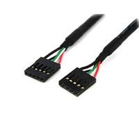
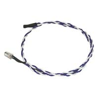
 I used StarTech's BEZELWRKIT ($6) plus their 18" Internal 5-pin USB Header Cable ($5) to fabricate a cable that connected the power LED, power button, and front USB. I bought some shrink tubing from my local Home Depot store to make the final cable look more professional. With the BEZELWRKIT you even have the leads labeled properly. I used a Lamptron 3mm tailed LED ($3: blue, white, or red) to provide a disk activity indicator.
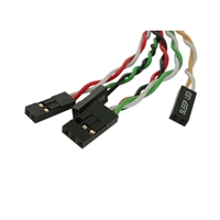

With the final result below:


You do need some soldering skill, but not the ability you'd need soldering motherboard components, and a small push pin is very useful for removing wires from the G5 front panel connector.
Tom
