Contribute
Register

Need advice if I don't want to cut the back plate

Status
Not open for further replies.
Joined
Feb 13, 2019
Messages
2
Motherboard
none
CPU
none
Graphics
none
Hello everyone!!!

I just brought a power mac g5 which I am thinking of turning it into a gaming hackintosh.

I want to do this mod but try to keep it as original as possible is there a way that I don't have to cut the backplate?

Thanks
 
Last edited:
My power mac is g5 7,2
 
Last edited:
Hi, well it depend how painfull way you wona go. There are copule of options how to do it described here already (you can check my build log for inspiration as well).
I think easiest way how to do it is place a psu on the ground of the case, make a extension cable from standard atx psu to apple psu connector, reuse original mobo standoffs and glue it to correct atx mobo position, then use USB pcie extension to get out 4 usb like this one:
https://www.amazon.com/dp/B00015Y0FK/?tag=tonymacx86com-20
Once you will have USB's, you can use USB ethernet adapter, USB audio adapter like those:
https://www.amazon.com/dp/B074F4JCK7/?tag=tonymacx86com-20

https://www.amazon.com/dp/B010L4IXUS/?tag=tonymacx86com-20
 
Last edited:
I want to do this mod but try to keep it as original as possible is there a way that I don't have to cut the backplate?

Hello!, can I point you to my G5 Build?. I too do not wish to cut my G5 case, so I have to think of creative ways to get around connecting USB3 and Ethernet. For the USB 3 I bought a travel USB 3 Hub with four slots, which is enough for my needs. I could just about connect it to the USB 3 slot on the Dell 7010 motherboard, If I remove the rear fan guard.
The Ethernet cable will fit into its slot but its tight. I have about 3/4 inch space between the back of the case and the motherboard. I'm looking at right angled or 90 degree ethernet and USB 3 cables which would make things much tidier.
 
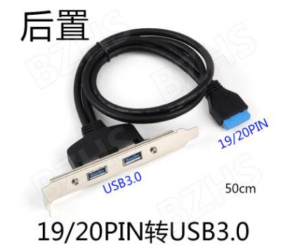
My own method is a bit cumbersome, ABS board, self-measurement NC processing. Purchase the various mating connectors separately, then solder the various extension cords yourself, put them directly into the slots, and fix the connectors with hot melt adhesive. But to do this, the motherboard needs to move backwards. The PCI card position socket of the graphics card requires a pair of connectors to match the PCI position of the chassis. This way, a PCI location is added. You can install one more PCI baffle with USB. Figure 3 is the pair of connectors, and Figure 4 is the PCI baffle. Make a reference.
Google translates Chinese to English. I hope you can read it, haha!
 

Attachments

  • O1CN01cWXCLD23YKitLXAQD_!!0-fleamarket.jpg_728x728.jpg
    O1CN01cWXCLD23YKitLXAQD_!!0-fleamarket.jpg_728x728.jpg
    358.2 KB · Views: 165
  • O1CN01pPuGmz1w5khKyz4sF_!!0-fleamarket.jpg_728x728.jpg
    O1CN01pPuGmz1w5khKyz4sF_!!0-fleamarket.jpg_728x728.jpg
    303.2 KB · Views: 183
  • BaiduShurufa_2019-4-8_15-46-16.jpg
    BaiduShurufa_2019-4-8_15-46-16.jpg
    42.6 KB · Views: 148
  • BaiduShurufa_2019-4-8_15-42-41.png
    BaiduShurufa_2019-4-8_15-42-41.png
    135.1 KB · Views: 127
Status
Not open for further replies.
Back
Top