
- Joined
- May 27, 2010
- Messages
- 2,364
- Motherboard
- Dell Optiplex 9030 All in One
- CPU
- i5-4690K
- Graphics
- HD 4600
- Mac
- Classic Mac
- Mobile Phone
Powermac G4 MDD
For quite a while I have liked the MDD powermac. To my mind it is the nicest looking of all the models of G4.

Unfortunately though it is considered to be the most tricky to convert to PC format. Here's why:


The rear panel goes "the wrong way". It is the opposite format to a PC.
Then, the CD drive area is right in the middle of the case meaning any conventional PC motherboard will in no way fit without ripping out the drives.
Over a year ago now I bought an empty MDD case for £15. At the time I had just assumed it'd be the same as any G4 to convert, but when I looked around the net and saw these problems I left it in the corner of a room marked "come back to one day".
When I finally took it out of the corner my first actions were to strip off the rear panel from the door, rip out the old drive supports etc and try this for size:

Then though as it was obvious I'd need to do a complete new rear panel I thought why not try this:

To get even to that stage though I had to cut a notch in the left hand side to get it to fit in. Also, going this way would mean I'd need to abandon the idea of having the board mounted on the door as I wanted to have all of the ports accessible....and the decision was then made. I'd not seen a G4 full ATX conversion where you coud actually get at all the slots and I thought this would make an interesting project.
My idea for this project then was to have the PSU and hard drives under the ATX board, the board would be on a purpose made motherboard tray on brackets and would be quickly removable by thumbscrews. By having this as a double deck arrangement I'd have freedom to make a completely new design.
The space for the original PSU is here:

I know that it is quite possible to re-mount a proper ATX power supply in a space 60mm deep from having to do that for G5 mod.s. The recessed area shown above is 7mm deep and 125mm wide so I found a full-ATX 550W PSU and trial fitted it:

Because I am using a 5mm perspex motherboard tray (very strong believe me) with a smooth underside and no metal parts on it, I am able to make as much use from the case as possible. This was my first mock up of an interior layout using a scrap board I got off eBay (someone had bent the CPU socket pins):

In my first mock up I was looking at whether it would be alright to do a flat rear panel and not have a I/O bracket. The motherboard tray would slide on brackets and PCI brackets would fix in place automatically as the tray slid to the back of the case. This worked okay, but I decided that I would prefer to use a conventional I/O bracket for this one.
So here is my revised design:

Here, I have cut the ledge that the original door used to close against and instead JB'd a channel of 8mm aluminium for the whole width of the case under where the ledge had been. This channel provides extra reinforcement to the panel and also to give extra headroom for graphics cards. The other reason for the channel though is so that when the motherboard tray slides into place the whole front edge is supported above and below inside the channel - the sides are held in place by a pair of thumbscrews and the front edge will have a thumbscrew securing that side too.....
All these reinforcements mean that when the case is stood upright the motherboard and all cards and heatsink etc "should" be held very securely in place. That's something I'll find out soon enough though I guess.
So, at the moment here are the bits and pieces in progress:

Perspex drive holder for 2 drives

Ventilaltion for the front - two 120mm fans

Support for the MOBO tray at the front with space for 2x60mm fans for PSU venting and on the other side vent holes for the drive area.

New rear panel.

My re-interpretation of the mirror front.

April 9:
Been meaning to upload a few pic.s for a while now. System is up and running but will change again soon.
Meantime, I thought you might like to see where it is at on the inside and under the motherboard.
Here's the whole motherboard assembled onto my 5mm acrylic tray and ready to go in as a unit:

The motherboard I settled on for this project is a Gigabyte GA-Z68XP-UD3P, processor is i5 2500K.

That massive cooler is a Noctua C-14 (I wanted something heavy in there to go alongside the Nvidia GTX 560Ti to make sure my engineering of the case and mobo mounts was good!!!).
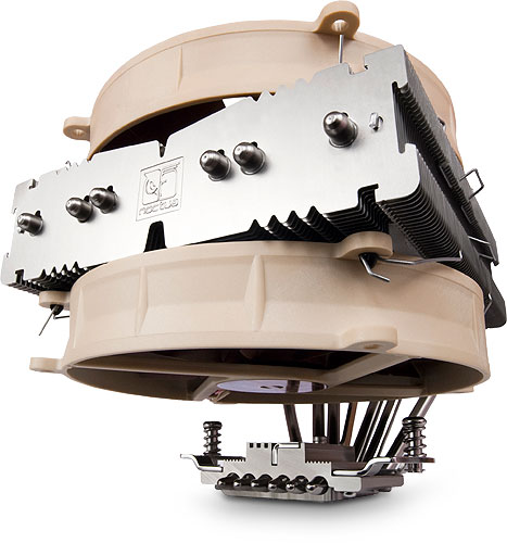
This cooler gets good reviews and can be used in various modes - with 2x 140 mm fans it is about as effective an air cooler as you can get - but with one underslung fan it will fit the MDD case in the way I'm using it.

This is a general under the hood shot. While the cable mass there looks excessive, you can see it is tied up to form a wall between psu area and disk carrier area. The idea is that when the mobo tray is on top of it air from the two 60mm Fractal design fans goes directly to the PSU and ventilates it exiting through the case holes at the back to keep it supplied with good cool air. Also you can feed some cables through holes in the MDD case to store between the perspex side panel and metal panels so you can have FULL ATX power supply in there.

The PSU I used is a Nexus Technology NX-5000:
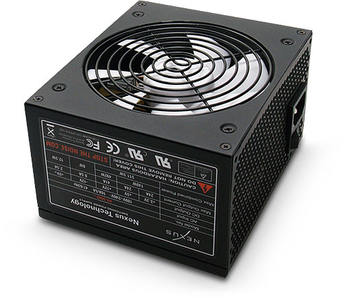
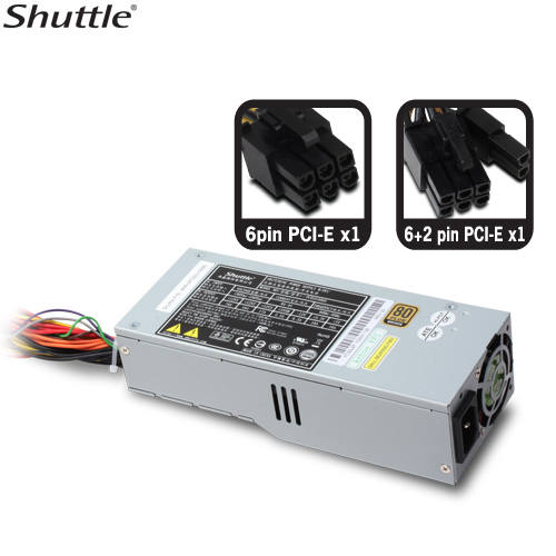
The PSU was fitted as per my trial fitting above - i.e. in similar fashion to what is done for G5 PSU mod.s, taken out of the case and the PCB mounted onto a Perspex carrier and bolted in place. Fan control for the Fractals comes from the PSU itself. There is a solid mechanical and electrical earth to the case and, of course, with the MOBO tray being thick perspex sealing off the top of the PSU from stray fingers is safe enough for me. If I were to make one for anybody else though I would instead use this as a solution:
Below is a view of the disk carrier area. It stands suspended above the case floor on high PCB standoffs. It changed slightly from my first design though and while you can see two 3.5"HDs there is also a 2.5" SSD attached underneath the 3.5" SD at the bottom of the picture. This carrier takes up to 2x 3.5 and 2x 2.5 disks. The HD storage area has air fed through the large vent holes to the left hand side of the 60mm perspex front fan mount and gets quite enough air from the front mounted fans.

Cooling in these cases is something that is always a factor. That's why I used the "spare" 140mm from the Noctua cooler as well as a 120mm fan at the front. The MDD has a meshed area built into it from stock at the front bottom, and the replacement of the useless MDD mirrored area with a mirrored honeycomb mesh and new front I/O effectively gives around 240mm of vented spaceto get loads of air in.

My one concern on air flow is actually the massive Noctua itself. As it sucks air down through the cooler and around the MOBO I am concerned it is not an optimal solution as the sheer size of it obstructs a clean front to back airflow in the area above the I/O bracket.
As you can see from the image below, having the HDDs and PSU under the mobo tray and a space at the front of my edge of the mobo for the main cables to exit gives a good cable management and allows a nice clean space at the very front of the case. Also the mobo tray has slots where needed in it so that, for instance, the CPU 12v connector can just appear at the right place instead of needing to be routed around other components.
You can also see from the image below (if you look closely) how the MOBO tray is mounted to the case. To the left edge of the mobo tray are two 3mm screws that go into the 10mm thick black perspex slab forming the divider and 60mm fan support. Now look above and below the mobo area you can see there is a thumbscrew and a small plate and those co-operate with L-shaped ledges formed from aluminium. To the right and hidden from view is the length of 8mm U channel I mentioned earlier.
So fixing the MOBO tray in place goes like this:
With the unit on it's side (easiest that way) - and on something nice and soft to protect the perspex outer trim panel - you put the mobo and assembled tray into the case and sit it on the L - shaped ledges. Then slide the tray assembly forward and engage the thumbscrews. Those screws slide in slots formed in the 5mm perspex tray and let the whole lot move towards the rear panel. Slide it to where the rear lip of the mobo is fully insdie the U-channel and then screw the two front 3mm fixings into place. Then make sure it is all nicely square and tighten the thumbscrew. It is then mounted and fixed on all four edges and isn't going anywhere...it's all surprisingly robust as an assembly and having just four fixing points means it is just a 5 minute job to place and remove.

That good clear vertical space at the front and my desire to have a lower profile block of stuff over the CPU (for front to back airflow) has though made me definitely thinking that this case will work awesomely with a front mounted Corsair H100.
Some more pic.s


14 April 2012
After some re-thinking and testing I got that H100 in there. Here is the adapter plate I made up:

The L-shaped cutout is to allow the I/O to pass through and also to give maximum airflow to the unit. The top part of the bracket is for mounting the power switch. Though the plate is ideal for mounting the H100 it also will allow any single 120mm fan to be mounted to the front of the MDD very easily.


The bracket as you can see fixes to the top fan and the other holes line up with where rivets were originally on the front panel (so there is no case cutting or new holes on the front of the metal case). The H100 is then bolted at the two lowermost fan holes to the meshed area at the front of the MDD.
The fan shroud forming part of the bracket has two purposes - one because I don't want to cut the mesh at the bottom of the MDD, it is needed to step the whole unit away from the front of the case and let it stand vertical and secondly by having it slightly back and with the shroud there you get better airflow from the two openings across the entire fan intake area.
All the holes that connect with the MDD front are threaded with brass M3 inserts that I heat up and insert into the acrylic with a soldering iron - gives a really robust thread that won't strip or pull out.
Here are the pic.s inside the case now:


Cooling, temperatures and overclocking
So, I have put some detail of this on my latest post, but to sum up this is what I have found about this case conversion and these components.
The Noctua cooler was holding this back. When tested in isolation before changing over to the H100 I found that under normal CPU settings (3.3GHz, no overclock) but running a 100% load test for two hours the case temp at the end was 39c and the average temp.s of the four cores were around 47 - which I felt fairly happy about. However, after stepping up to the H100 I was able to overclock to 4.4GHz and run the same load tests and get a case temp of 37 and CPU cores averaging out at 46 and that was using the H100 in the second of the three modes - i.e. not maxed out and still fairly quiet. Idle temps at the overclock with the H100 are all better than the idle temps at 3.3GHz with the Noctua config. So effectively that is a 3000 point Geekbench improvement with everything running cooler than at previous stock settings.
From this, I am not saying the Noctua is a bad cooler, as it does a good job, but that the H100 works much better in my case partly because the cooler is awesome, but also partly because it is lower profile so allows a better front to back airflow. And the cooling is not compromised by having the radiator front mounted.
This build is now more or less completed. I will be doing a few cosmetic things though like try out another back plane design and tweak the front design a little.
If I get time and the video function on my Samsung phone permits I may make a short video of the modded case.
Hope you liked the mod. and my new way of hacking the MDD case. On this one, there are actually surprisingly few bits of metalwork needed as the perspex parts I have made for the most part to ft into holes where I drilled out rivets. So while it may look complicated, once the perspex bits are to hand it's not as hard as it might look. And, of course, I do have all the laser files to be able to do more.
For quite a while I have liked the MDD powermac. To my mind it is the nicest looking of all the models of G4.
Unfortunately though it is considered to be the most tricky to convert to PC format. Here's why:
The rear panel goes "the wrong way". It is the opposite format to a PC.
Then, the CD drive area is right in the middle of the case meaning any conventional PC motherboard will in no way fit without ripping out the drives.
Over a year ago now I bought an empty MDD case for £15. At the time I had just assumed it'd be the same as any G4 to convert, but when I looked around the net and saw these problems I left it in the corner of a room marked "come back to one day".
When I finally took it out of the corner my first actions were to strip off the rear panel from the door, rip out the old drive supports etc and try this for size:
Then though as it was obvious I'd need to do a complete new rear panel I thought why not try this:
To get even to that stage though I had to cut a notch in the left hand side to get it to fit in. Also, going this way would mean I'd need to abandon the idea of having the board mounted on the door as I wanted to have all of the ports accessible....and the decision was then made. I'd not seen a G4 full ATX conversion where you coud actually get at all the slots and I thought this would make an interesting project.
My idea for this project then was to have the PSU and hard drives under the ATX board, the board would be on a purpose made motherboard tray on brackets and would be quickly removable by thumbscrews. By having this as a double deck arrangement I'd have freedom to make a completely new design.
The space for the original PSU is here:
I know that it is quite possible to re-mount a proper ATX power supply in a space 60mm deep from having to do that for G5 mod.s. The recessed area shown above is 7mm deep and 125mm wide so I found a full-ATX 550W PSU and trial fitted it:
Because I am using a 5mm perspex motherboard tray (very strong believe me) with a smooth underside and no metal parts on it, I am able to make as much use from the case as possible. This was my first mock up of an interior layout using a scrap board I got off eBay (someone had bent the CPU socket pins):
In my first mock up I was looking at whether it would be alright to do a flat rear panel and not have a I/O bracket. The motherboard tray would slide on brackets and PCI brackets would fix in place automatically as the tray slid to the back of the case. This worked okay, but I decided that I would prefer to use a conventional I/O bracket for this one.
So here is my revised design:
Here, I have cut the ledge that the original door used to close against and instead JB'd a channel of 8mm aluminium for the whole width of the case under where the ledge had been. This channel provides extra reinforcement to the panel and also to give extra headroom for graphics cards. The other reason for the channel though is so that when the motherboard tray slides into place the whole front edge is supported above and below inside the channel - the sides are held in place by a pair of thumbscrews and the front edge will have a thumbscrew securing that side too.....
All these reinforcements mean that when the case is stood upright the motherboard and all cards and heatsink etc "should" be held very securely in place. That's something I'll find out soon enough though I guess.
So, at the moment here are the bits and pieces in progress:
Perspex drive holder for 2 drives
Ventilaltion for the front - two 120mm fans
Support for the MOBO tray at the front with space for 2x60mm fans for PSU venting and on the other side vent holes for the drive area.
New rear panel.
My re-interpretation of the mirror front.
April 9:
Been meaning to upload a few pic.s for a while now. System is up and running but will change again soon.
Meantime, I thought you might like to see where it is at on the inside and under the motherboard.
Here's the whole motherboard assembled onto my 5mm acrylic tray and ready to go in as a unit:
The motherboard I settled on for this project is a Gigabyte GA-Z68XP-UD3P, processor is i5 2500K.
That massive cooler is a Noctua C-14 (I wanted something heavy in there to go alongside the Nvidia GTX 560Ti to make sure my engineering of the case and mobo mounts was good!!!).
This cooler gets good reviews and can be used in various modes - with 2x 140 mm fans it is about as effective an air cooler as you can get - but with one underslung fan it will fit the MDD case in the way I'm using it.
This is a general under the hood shot. While the cable mass there looks excessive, you can see it is tied up to form a wall between psu area and disk carrier area. The idea is that when the mobo tray is on top of it air from the two 60mm Fractal design fans goes directly to the PSU and ventilates it exiting through the case holes at the back to keep it supplied with good cool air. Also you can feed some cables through holes in the MDD case to store between the perspex side panel and metal panels so you can have FULL ATX power supply in there.
The PSU I used is a Nexus Technology NX-5000:
The PSU was fitted as per my trial fitting above - i.e. in similar fashion to what is done for G5 PSU mod.s, taken out of the case and the PCB mounted onto a Perspex carrier and bolted in place. Fan control for the Fractals comes from the PSU itself. There is a solid mechanical and electrical earth to the case and, of course, with the MOBO tray being thick perspex sealing off the top of the PSU from stray fingers is safe enough for me. If I were to make one for anybody else though I would instead use this as a solution:
Below is a view of the disk carrier area. It stands suspended above the case floor on high PCB standoffs. It changed slightly from my first design though and while you can see two 3.5"HDs there is also a 2.5" SSD attached underneath the 3.5" SD at the bottom of the picture. This carrier takes up to 2x 3.5 and 2x 2.5 disks. The HD storage area has air fed through the large vent holes to the left hand side of the 60mm perspex front fan mount and gets quite enough air from the front mounted fans.
Cooling in these cases is something that is always a factor. That's why I used the "spare" 140mm from the Noctua cooler as well as a 120mm fan at the front. The MDD has a meshed area built into it from stock at the front bottom, and the replacement of the useless MDD mirrored area with a mirrored honeycomb mesh and new front I/O effectively gives around 240mm of vented spaceto get loads of air in.
My one concern on air flow is actually the massive Noctua itself. As it sucks air down through the cooler and around the MOBO I am concerned it is not an optimal solution as the sheer size of it obstructs a clean front to back airflow in the area above the I/O bracket.
As you can see from the image below, having the HDDs and PSU under the mobo tray and a space at the front of my edge of the mobo for the main cables to exit gives a good cable management and allows a nice clean space at the very front of the case. Also the mobo tray has slots where needed in it so that, for instance, the CPU 12v connector can just appear at the right place instead of needing to be routed around other components.
You can also see from the image below (if you look closely) how the MOBO tray is mounted to the case. To the left edge of the mobo tray are two 3mm screws that go into the 10mm thick black perspex slab forming the divider and 60mm fan support. Now look above and below the mobo area you can see there is a thumbscrew and a small plate and those co-operate with L-shaped ledges formed from aluminium. To the right and hidden from view is the length of 8mm U channel I mentioned earlier.
So fixing the MOBO tray in place goes like this:
With the unit on it's side (easiest that way) - and on something nice and soft to protect the perspex outer trim panel - you put the mobo and assembled tray into the case and sit it on the L - shaped ledges. Then slide the tray assembly forward and engage the thumbscrews. Those screws slide in slots formed in the 5mm perspex tray and let the whole lot move towards the rear panel. Slide it to where the rear lip of the mobo is fully insdie the U-channel and then screw the two front 3mm fixings into place. Then make sure it is all nicely square and tighten the thumbscrew. It is then mounted and fixed on all four edges and isn't going anywhere...it's all surprisingly robust as an assembly and having just four fixing points means it is just a 5 minute job to place and remove.
That good clear vertical space at the front and my desire to have a lower profile block of stuff over the CPU (for front to back airflow) has though made me definitely thinking that this case will work awesomely with a front mounted Corsair H100.
Some more pic.s
14 April 2012
After some re-thinking and testing I got that H100 in there. Here is the adapter plate I made up:
The L-shaped cutout is to allow the I/O to pass through and also to give maximum airflow to the unit. The top part of the bracket is for mounting the power switch. Though the plate is ideal for mounting the H100 it also will allow any single 120mm fan to be mounted to the front of the MDD very easily.
The bracket as you can see fixes to the top fan and the other holes line up with where rivets were originally on the front panel (so there is no case cutting or new holes on the front of the metal case). The H100 is then bolted at the two lowermost fan holes to the meshed area at the front of the MDD.
The fan shroud forming part of the bracket has two purposes - one because I don't want to cut the mesh at the bottom of the MDD, it is needed to step the whole unit away from the front of the case and let it stand vertical and secondly by having it slightly back and with the shroud there you get better airflow from the two openings across the entire fan intake area.
All the holes that connect with the MDD front are threaded with brass M3 inserts that I heat up and insert into the acrylic with a soldering iron - gives a really robust thread that won't strip or pull out.
Here are the pic.s inside the case now:
Cooling, temperatures and overclocking
So, I have put some detail of this on my latest post, but to sum up this is what I have found about this case conversion and these components.
The Noctua cooler was holding this back. When tested in isolation before changing over to the H100 I found that under normal CPU settings (3.3GHz, no overclock) but running a 100% load test for two hours the case temp at the end was 39c and the average temp.s of the four cores were around 47 - which I felt fairly happy about. However, after stepping up to the H100 I was able to overclock to 4.4GHz and run the same load tests and get a case temp of 37 and CPU cores averaging out at 46 and that was using the H100 in the second of the three modes - i.e. not maxed out and still fairly quiet. Idle temps at the overclock with the H100 are all better than the idle temps at 3.3GHz with the Noctua config. So effectively that is a 3000 point Geekbench improvement with everything running cooler than at previous stock settings.
From this, I am not saying the Noctua is a bad cooler, as it does a good job, but that the H100 works much better in my case partly because the cooler is awesome, but also partly because it is lower profile so allows a better front to back airflow. And the cooling is not compromised by having the radiator front mounted.
This build is now more or less completed. I will be doing a few cosmetic things though like try out another back plane design and tweak the front design a little.
If I get time and the video function on my Samsung phone permits I may make a short video of the modded case.
Hope you liked the mod. and my new way of hacking the MDD case. On this one, there are actually surprisingly few bits of metalwork needed as the perspex parts I have made for the most part to ft into holes where I drilled out rivets. So while it may look complicated, once the perspex bits are to hand it's not as hard as it might look. And, of course, I do have all the laser files to be able to do more.
")