Why do you not just use the original power supply?
(Short answer: You may need to fake the POWER_GOOD signal.)
I just rewired the PSU from a 1.8 GHz uniprocessor G5 and tested it with PC motherboards. It works fine with a Intel® Desktop Board D946GZIS. See picture below, but read comments about Power_good at end of post.

(Photo: Intel® Desktop Board D946GZIS, rewired G5 power supply and a start button.)
There are two ways of rewiring the power supply. I chose the difficult one, but later decided that there is not really a need to even open the PSU, except maybe for cleaning.
This is what I did: I removed all the wires from the 24-pin (P1) and 16-pin (P2) connectors using pilers and staples. I left the 8-pin drive bay connector (P3) as it is. This gives power to the hard drives and SuperDrive DVD.
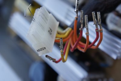
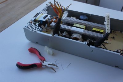
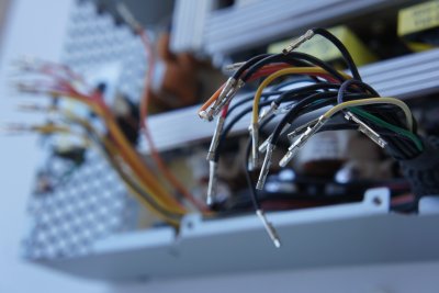
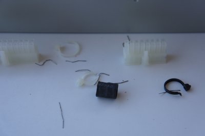
I then grouped the wires by color, separating the v1 and v2 12 volt phases.
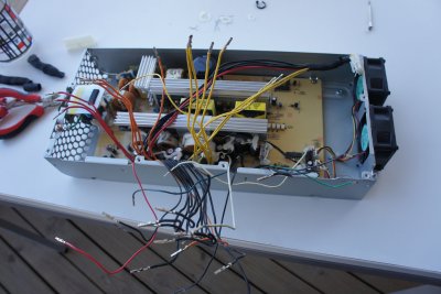
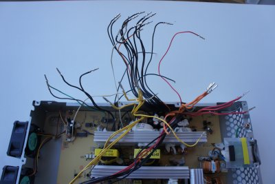
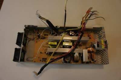
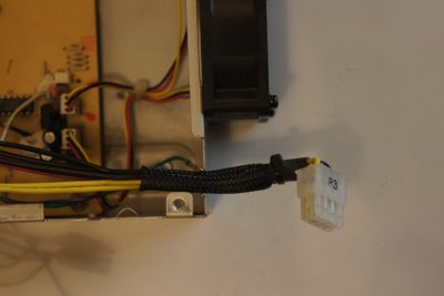
I rewired them for PC use:
1) I used two 12 volt wires from phase v1 and two ground wires for a 4-pin motherboard P4 power connector.
2) I used three 12 volt wires from phase v3 and three ground wires for a 6-pin PCI-E power connector.
3) I pushed the three unneeded wires, 25 volt, fan tacho and on ground wire into the unused 16-pin connector and attacred it into the inside of the PSU case.
4) All the other wires I connected to the original 24-pin connector using the ATX wiring scheme. The Molex Mini-Fit Jr.™ connector is exactly the same with the same keying as used on ATX motherboards.
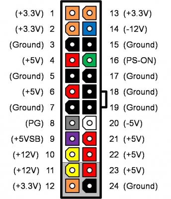
- I was two red 5 volts short of the ATX pinout. I connected the Mac-specific 5 volt sense signal to one of the extra 5 volt pins, hoping they are all connected on the motherboard.
- I cut the 3.3 volt sense wire and soldered it to 3.3 vise on pin 2, as it is usually done in ATX power supplies.
- The Mac PSU provides no Power_Good (PG) signal, so I left pin 8 unconnected.
I was hoping I could keep the 24-pin connector in the same position at the center of the power supply, but as most of the wires come from old 16-pin connector, I had to move the 24-pin connector to its place at the back end of the PSU. I had to solder some extra wire to the green Power_ON wire and the violet 5 volt standby wire to make them long enough for the new position.
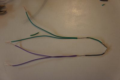

Testing the power supply:
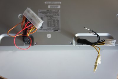
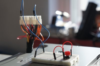
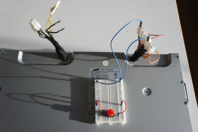
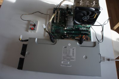
I was hoping that the wires would end up long enough to reach the motherboard connectors. This might work if I was using a server-type motherboard with the connectors at the bottom edge (top, in normal server installations). In the end I had to buy extension cords for the power connectors.
I simpler way of modifying the PSU would be to leave it exactly as it is and do the rewiring in a wiring harness. Get 30 cm extension pieces for all the PC connectors and remove the male pins from the side of the PSU. Reconnect the wires according to the mapping from the ATX pinout to the the Power Mac pinout. If you cannot find a 16-pin male connector, use a another 24-pin male connector. (It fits in two positions.)
Faking Power Good
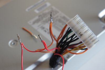
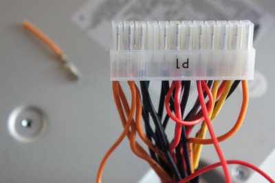
I tried different ways of faking the PG signal: connection directly to 5 volts or puting a 1 kiloohm resitor in between. All produced equally bad or good results. It turns out that the Intel desktop board did not care about the PG signal. Evidently it generates its own "power good" signal on the motherboard.
My Gigabyte GA-EG41MFT-US2H motherboard produced the opposite result. If I try to fake the PG signal by connecting pin 8 to 5 volts, the motherboard would start power cycling, turning the PSU on and off twice every second. It is however possible to boot the computer by pulling pin 8 to 5 volts at any time after power on with the CPU fan already spinning.


