
- Joined
- Jul 18, 2013
- Messages
- 3
- Motherboard
- Mac OSX/ Win 8/ Win 7
- CPU
- i5 3570K
- Graphics
- nvidia GeForce 660Ti
- Mac
- Classic Mac
- Mobile Phone
Hi all, this is my first post but I have been reading parts of the forum for tips for this mod and now that I have finished, I would like to share my process. Hopefully this will be helpful to anyone who reads this. This is my first ever mod, so please excuse my crap workmanship lol 
I wanted to keep it looking as original as possible apart from a new paint job. I have read that the G4 is not the best for air circulation, so I must consider possibilities for where I can draw air in. So this is what I have to put inside:
Like new Apple laptops, I have not decided to put any DVD drives. This will save space and improve airflow. The build was fun and was not too difficult. A rotary tool is a must! So to start off, I got myself a G4 for £20.

Obligatory picture of the original G4 before modding")
So first thing is to remove all the panels and take out all the insides. I kept the plastic bottom that is for the latch.

After a quick clean and dust there was a metal block that helped keep the plastic latch in place. This had to go because it would touch the motherboard I want is. I also used my dremel to cut off the apple motherboard standoffs.

I removed the block by using a razor blade shown in the picture. I put it in the corner and used a hammer to tap against it. Soon it cut into the adhesive and the block came off.
The next thing I did was to paint the plastic panels. I went for a matt white spray paint and matt black for the apple logo. There are many guides on how to paint these. The short story is I sanded the surface using wet sanding paper 400 Grit, then 600 Grit. As it is a matt surface, I didn't bother with anything higher than this grit. If you do want a smoother surface, use a higher grit. 2 layers of primer then 2-3 layers of the colour spray. I guess, I could of spent more time on these part to make it look more professional, but my patience grew thin lol.


The next part for me was to get the motherboard mounted in the correct place. I aligned the motherboard WITH the graphics card on so that the graphics would mount on the original slots. This would give a neater install and overall look.Using a pen, I marked all the standoff points. Using a 3mm drill bit, I drilled the holes for the standoffs and this is the perfect size for the standard brass standoffs. It was tight enough to screw in. However, because there are no threads, it wouldn't be very secure. After I was happy with the standoffs, I used standard super glue on the outer-side to keep the standoffs in place.
Before fitting the motherboard, the back panel does not fit the back panel of the motherboard. So I cut the panel as seen on the picture. I cut the small metal part that covered the holes for the sound. When it was large enough for the ports on the motherboard, I mounted the motherboard with the graphics to see if it fits. Thank god it did! However, 1 or 2 of the standoffs might have missed the mark haha. But it didn't affect it much.

Back Panel with graphics fitted on

Different angle, Notice the inside shelf
There was something attached to inner side that was held on via rivets. So I drilled out the rivets. The shelf part in the case where the PSU sits is too large. I only need a small part for the PSU to sit on. The PSU fan is facing solid metal at the moment, it has like 1cm clearance. This will not be great for airflow. So I cut a hole where the fan is to allow a bit more air flow. I removed the DVD bracket as I am not using any DVD drives.
The next problem I had was the H60 cooler and how to mount it. It was too short to mount it in the main part of the case, because when it flips down. The pipes do not stretch far enough. I put this problem aside for now, the next part I worked on was the plastic latch. The new standoffs will not allow it to go back on. So some drilling and sanding later, the plastic was cut to allow it to slide too. Another issue is the bottom side of the motherboard has the bracket for the cooler. This affected the plastic, so more was needed to be cut.
I mounted everything down and put graphics card on, turned on the computer. It Worked! for 5 minutes. Turns out the motherboard was a bit too low and the graphics card couldn't get a nice fit. So I used plastic washers to push the motherboard an extra 1-2mm. This worked a charm.
So now I have the problem of mounting the H60 radiator. The idea I went with was to make a 90 degree bracket to mount the radiator onto and when closed, it points the radiator downwards. To make this effective, I cut out 2 large holes at the bottom of the case. When closed the radiator would draw air from these holes. I used a blank CD and marked around it. It seems a perfect size for a 120mm fan.


The bracket itself was made from the bracket that held the original 120mm fan to the size of the case. I took this and bent it at 90 degrees. I cut off the excess and drilled holes through the bracket into the case. A couple of nut and bolts and dremel off the excess bolt. The holes are already for a 120mm, so no extra work to be done. Worked great. And when it is closed it pointed the radiator at the bottom hole. Perfect
I put another 120mm fan on the other hole to draw air up from the bottom as cold air is from the bottom right? well it blows it onto the graphics card, which has the twin fozr heat sinks on along with its 2 fans.

Onto the front panel! I plan to use the original buttons and panel and led. Looking online, there were a few examples of it being done. None too clear though mind, probably due to the subtle differences between model. Mine is from the G4 graphite. I worked out where to solder the wires. The Wires were from the internet ordered to just test motherboards. It has the jumpers already on them. Alternatively, you can make them yourself. But why bother going through the hassle when 1 quid will buy you a set inc buttons and LED.


Finally to add an extra touch to the build, I used the translucent Apple logo near the top and put a white LED behind it. Instead of soldering an LED wire into the power panel etc. I just bought a molex to single LED. Cheap easy, and quite neat. I drilled a 5mm hole for the 5mm LED, and it worked when turned on. However, I found this too bright and it looked like a white spot in an Apple logo. I needed to diffuse this bright light. I did this by sanding the LED itself using 400 Grit. I got a rough surface and it worked well and better. But still too bright. This time I cheated and put a folded up piece of paper in front of the LED to help diffuse it evenly. This worked well.
Nearing the end, I put everything back together and closed up the side. Put all the plastic casing back on. Notice the legs raises the bottom up for air to go in. The back had the problem where the plasic cover where the metal bit covered the audio ports, it covered the audio ports. But instead of cutting the middle part of it off. i sanded it down to allow access to the audio ports.


 Before diffusing the LED, notice how bright it is
 After diffusing the LED with paper, much better and even lighting
Turned it on and DONE! .
Running Prime95 overnight to see how hot it can get. 69C was the hottest. MSI kombustor for the graphics and that gave standard hot graphics readings. The ambient idle temp was 8-10C more than Room temperature.
Overclocking the i3570K to 4.2Ghz per core only upped it by 1-2C but still maxes at 69C.
Sound is pretty silent, a low hum from the graphics card fans. Maybe if I converted this build to a full watercooled, it would be silent.
Other improvements would be sound absorbing foam pads to reduce vibration from the case. I also want to paint the inside black for it to be better thermal conduction and also it looks cool
I wanted to keep it looking as original as possible apart from a new paint job. I have read that the G4 is not the best for air circulation, so I must consider possibilities for where I can draw air in. So this is what I have to put inside:
- i5 3570K OC to 4.2Ghz
- Gigabyte G1.Sniper.M3 mATX motherboard
- Corsair Vengeance 1886MHz 16GB RAM
- Corsair TX650 semi modular PSU
- MSI geforce 660Ti Power edition with Twin Fozr
- Corsair H60 water cooler for the processor
Like new Apple laptops, I have not decided to put any DVD drives. This will save space and improve airflow. The build was fun and was not too difficult. A rotary tool is a must! So to start off, I got myself a G4 for £20.
Obligatory picture of the original G4 before modding
So first thing is to remove all the panels and take out all the insides. I kept the plastic bottom that is for the latch.
After a quick clean and dust there was a metal block that helped keep the plastic latch in place. This had to go because it would touch the motherboard I want is. I also used my dremel to cut off the apple motherboard standoffs.
I removed the block by using a razor blade shown in the picture. I put it in the corner and used a hammer to tap against it. Soon it cut into the adhesive and the block came off.
The next thing I did was to paint the plastic panels. I went for a matt white spray paint and matt black for the apple logo. There are many guides on how to paint these. The short story is I sanded the surface using wet sanding paper 400 Grit, then 600 Grit. As it is a matt surface, I didn't bother with anything higher than this grit. If you do want a smoother surface, use a higher grit. 2 layers of primer then 2-3 layers of the colour spray. I guess, I could of spent more time on these part to make it look more professional, but my patience grew thin lol.
The next part for me was to get the motherboard mounted in the correct place. I aligned the motherboard WITH the graphics card on so that the graphics would mount on the original slots. This would give a neater install and overall look.Using a pen, I marked all the standoff points. Using a 3mm drill bit, I drilled the holes for the standoffs and this is the perfect size for the standard brass standoffs. It was tight enough to screw in. However, because there are no threads, it wouldn't be very secure. After I was happy with the standoffs, I used standard super glue on the outer-side to keep the standoffs in place.
Before fitting the motherboard, the back panel does not fit the back panel of the motherboard. So I cut the panel as seen on the picture. I cut the small metal part that covered the holes for the sound. When it was large enough for the ports on the motherboard, I mounted the motherboard with the graphics to see if it fits. Thank god it did! However, 1 or 2 of the standoffs might have missed the mark haha. But it didn't affect it much.
Back Panel with graphics fitted on
Different angle, Notice the inside shelf
There was something attached to inner side that was held on via rivets. So I drilled out the rivets. The shelf part in the case where the PSU sits is too large. I only need a small part for the PSU to sit on. The PSU fan is facing solid metal at the moment, it has like 1cm clearance. This will not be great for airflow. So I cut a hole where the fan is to allow a bit more air flow. I removed the DVD bracket as I am not using any DVD drives.
The next problem I had was the H60 cooler and how to mount it. It was too short to mount it in the main part of the case, because when it flips down. The pipes do not stretch far enough. I put this problem aside for now, the next part I worked on was the plastic latch. The new standoffs will not allow it to go back on. So some drilling and sanding later, the plastic was cut to allow it to slide too. Another issue is the bottom side of the motherboard has the bracket for the cooler. This affected the plastic, so more was needed to be cut.
I mounted everything down and put graphics card on, turned on the computer. It Worked! for 5 minutes. Turns out the motherboard was a bit too low and the graphics card couldn't get a nice fit. So I used plastic washers to push the motherboard an extra 1-2mm. This worked a charm.
So now I have the problem of mounting the H60 radiator. The idea I went with was to make a 90 degree bracket to mount the radiator onto and when closed, it points the radiator downwards. To make this effective, I cut out 2 large holes at the bottom of the case. When closed the radiator would draw air from these holes. I used a blank CD and marked around it. It seems a perfect size for a 120mm fan.
The bracket itself was made from the bracket that held the original 120mm fan to the size of the case. I took this and bent it at 90 degrees. I cut off the excess and drilled holes through the bracket into the case. A couple of nut and bolts and dremel off the excess bolt. The holes are already for a 120mm, so no extra work to be done. Worked great. And when it is closed it pointed the radiator at the bottom hole. Perfect
I put another 120mm fan on the other hole to draw air up from the bottom as cold air is from the bottom right? well it blows it onto the graphics card, which has the twin fozr heat sinks on along with its 2 fans.
Onto the front panel! I plan to use the original buttons and panel and led. Looking online, there were a few examples of it being done. None too clear though mind, probably due to the subtle differences between model. Mine is from the G4 graphite. I worked out where to solder the wires. The Wires were from the internet ordered to just test motherboards. It has the jumpers already on them. Alternatively, you can make them yourself. But why bother going through the hassle when 1 quid will buy you a set inc buttons and LED.
Finally to add an extra touch to the build, I used the translucent Apple logo near the top and put a white LED behind it. Instead of soldering an LED wire into the power panel etc. I just bought a molex to single LED. Cheap easy, and quite neat. I drilled a 5mm hole for the 5mm LED, and it worked when turned on. However, I found this too bright and it looked like a white spot in an Apple logo. I needed to diffuse this bright light. I did this by sanding the LED itself using 400 Grit. I got a rough surface and it worked well and better. But still too bright. This time I cheated and put a folded up piece of paper in front of the LED to help diffuse it evenly. This worked well.
Nearing the end, I put everything back together and closed up the side. Put all the plastic casing back on. Notice the legs raises the bottom up for air to go in. The back had the problem where the plasic cover where the metal bit covered the audio ports, it covered the audio ports. But instead of cutting the middle part of it off. i sanded it down to allow access to the audio ports.
Before diffusing the LED, notice how bright it is After diffusing the LED with paper, much better and even lightingTurned it on and DONE! .
Running Prime95 overnight to see how hot it can get. 69C was the hottest. MSI kombustor for the graphics and that gave standard hot graphics readings. The ambient idle temp was 8-10C more than Room temperature.
Overclocking the i3570K to 4.2Ghz per core only upped it by 1-2C but still maxes at 69C.
Sound is pretty silent, a low hum from the graphics card fans. Maybe if I converted this build to a full watercooled, it would be silent.
Other improvements would be sound absorbing foam pads to reduce vibration from the case. I also want to paint the inside black for it to be better thermal conduction and also it looks cool
Attachments
-
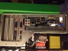 image-22.jpg20.9 KB · Views: 224
 -
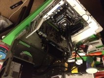 image-24.jpg21.3 KB · Views: 198
 -
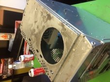 image-29.jpg21.4 KB · Views: 202
 -
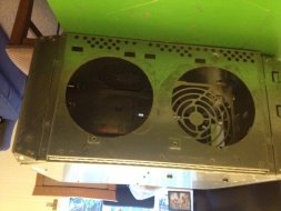 image-31.jpg20.1 KB · Views: 184
 -
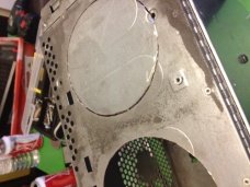 image-48.jpg21 KB · Views: 191
 -
 image-19.jpg18.4 KB · Views: 183
 -
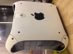 image-26.jpg18.9 KB · Views: 204
 -
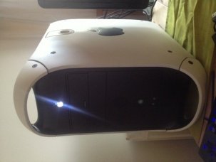 image-34.jpg18.6 KB · Views: 198
 -
 image-41.jpg19 KB · Views: 194
 -
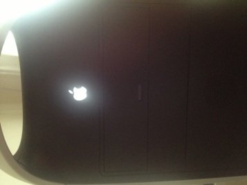 image-43.jpg19.1 KB · Views: 196
 -
 image-45.jpg19.3 KB · Views: 241


