- Joined
- Nov 16, 2010
- Messages
- 38
- Motherboard
- 10.7.4
- CPU
- i5 760
- Graphics
- gtx 285
- Mac
- Classic Mac
- Mobile Phone
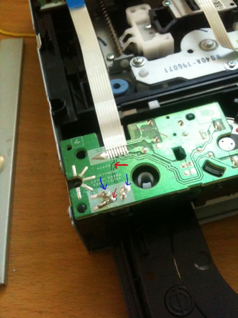
powerpcg5 said:Did you use a QT1040 chip?
I like your mod very much.... I like how the rear panel of the G5 was kept intact.
I'm thinking along those lines too... I know it's going to be more difficult (labor intensive) than just buying a mobo tray.
Love the L-bracket you made for the speaker and fan. Brilliant!
it is AT42QT1010...only single channel. got 25 of them from china. real cheap.
nige2000 said:good to see some raw innovation, and the no fear approach to the soldering iron
great post
thanks. it is only a few soldering...
no problem. which circuit do you need. actually. they are very sample and most of them have diagrams on the data sheet.belcboo said:Could you put the diagrams of the devices that you built and mod for your G5 case mod?... I'm thinking in build my own g5, and i think that your diagrams could be very useful, for me and for all who want build your own g5 mod's.
I hope you can do it. Regards
entouchgraphics said:WOW!!!! I absolutely LOVE this mod... My favorite of them all. I plan on doing something similar, just possibly with my own home made PCB for the I/O's, or maybe not haha idk..
Could you however elaborate on how much room there is between the I/O holes on the case itself and the ports on the Mobo if mounted flush to the PCI ports like yours is? I just want an estimate of how much room there is to work with...
And I am not trying to be picky, but, do you maybe have a pin-out diagram of the I/O's?
Thanks man!
really no much space...if you keep the apple rear io. there is only 3mm-5mm gap
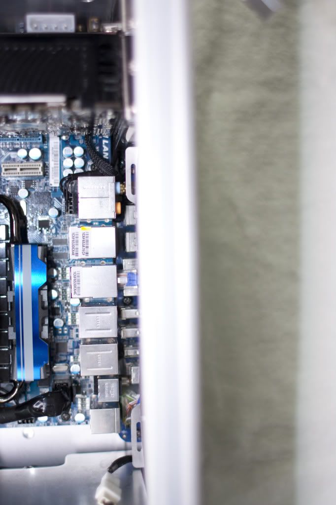
and you cannot use the fw800 port, if you keep the coaxial port....