Contribute
Register

Ersterhernd's NUCiMac G4

Status
Not open for further replies.
Completed the 2nd NUCiMac today, except for the touch-sensor brightness control. Still waiting for the Picaxe controller chip to arrive, but I've got all the rough wiring in the iMac ready to go. I bought another DC3217IYE i3 NUC yesterday, so I could complete the build. The performance is so terrific that I really couldn't justify spending any more on the i5 version. A few pics of the final steps.


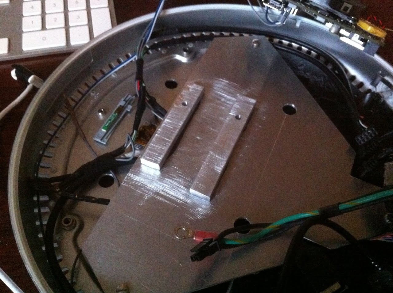
Threaded mount bars to bolt down the NUC

IMG_4204.JPG


The NUC base bolted to the iMac base plate

IMG_4205.JPG


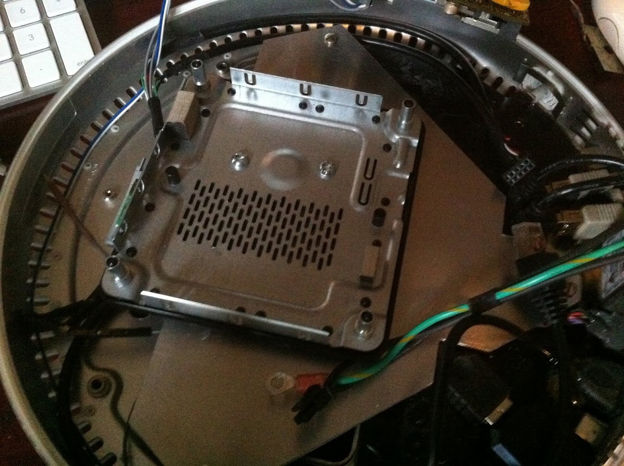
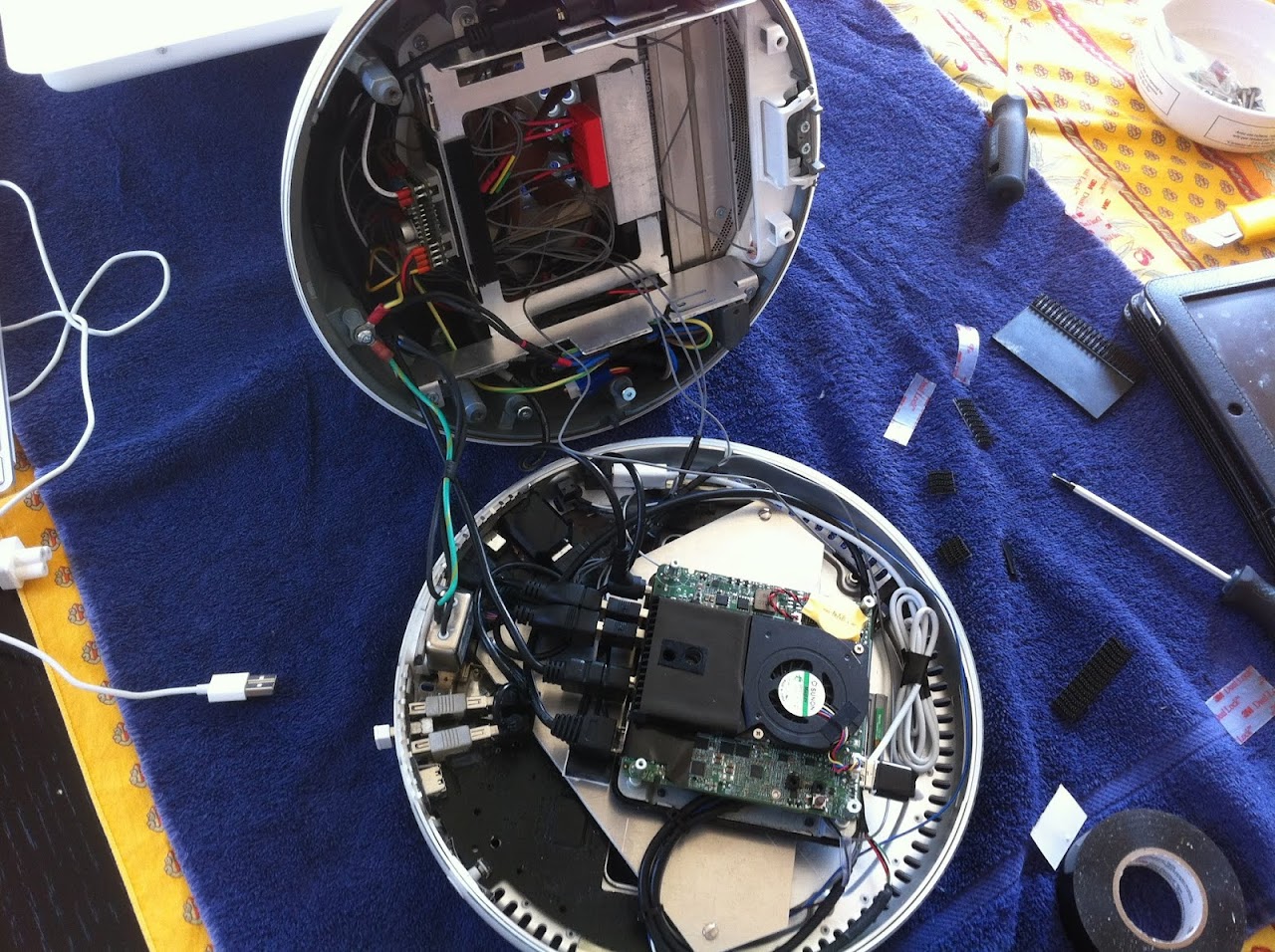
The NUC motherboard secured with its own standoffs removed from it's stock case

IMG_4207.JPG


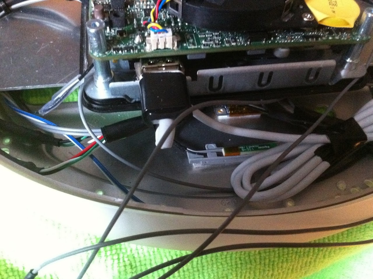
The HDMI to DVI converter secured with all the TMDS wires attached from the iMac neck. The 17 fragile wires are tucked safely out of the way so nothing will touch them.

IMG_4213.JPG


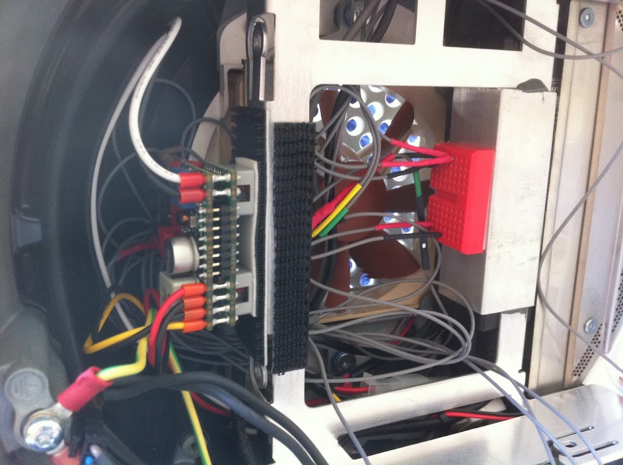
The PicoPSU fully wired up. I have every wire color coded for the correct power connection to avoid risk of a costly mistake!

IMG_4209.JPG


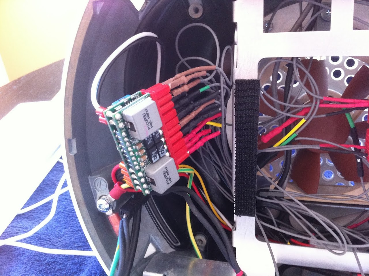
The Pico in it's secured position and the red breadboard wired up for the Picaxe micro-controller chip when it arrives. For now, I have the LCD inverter wired to 3.3V on the Pico.

IMG_4215.JPG


Ready to bolt up. All wiring completed.

IMG_4217.JPG


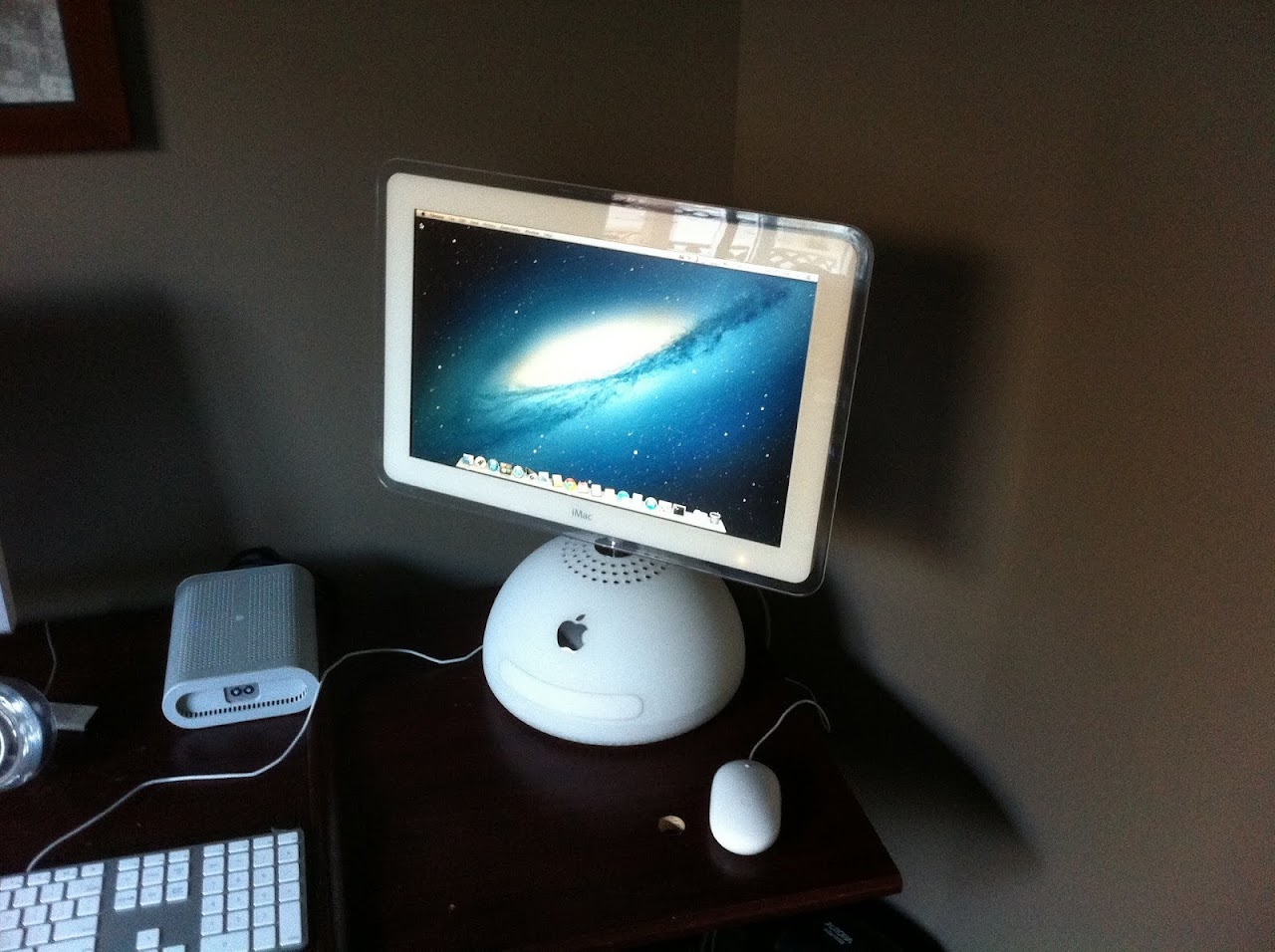
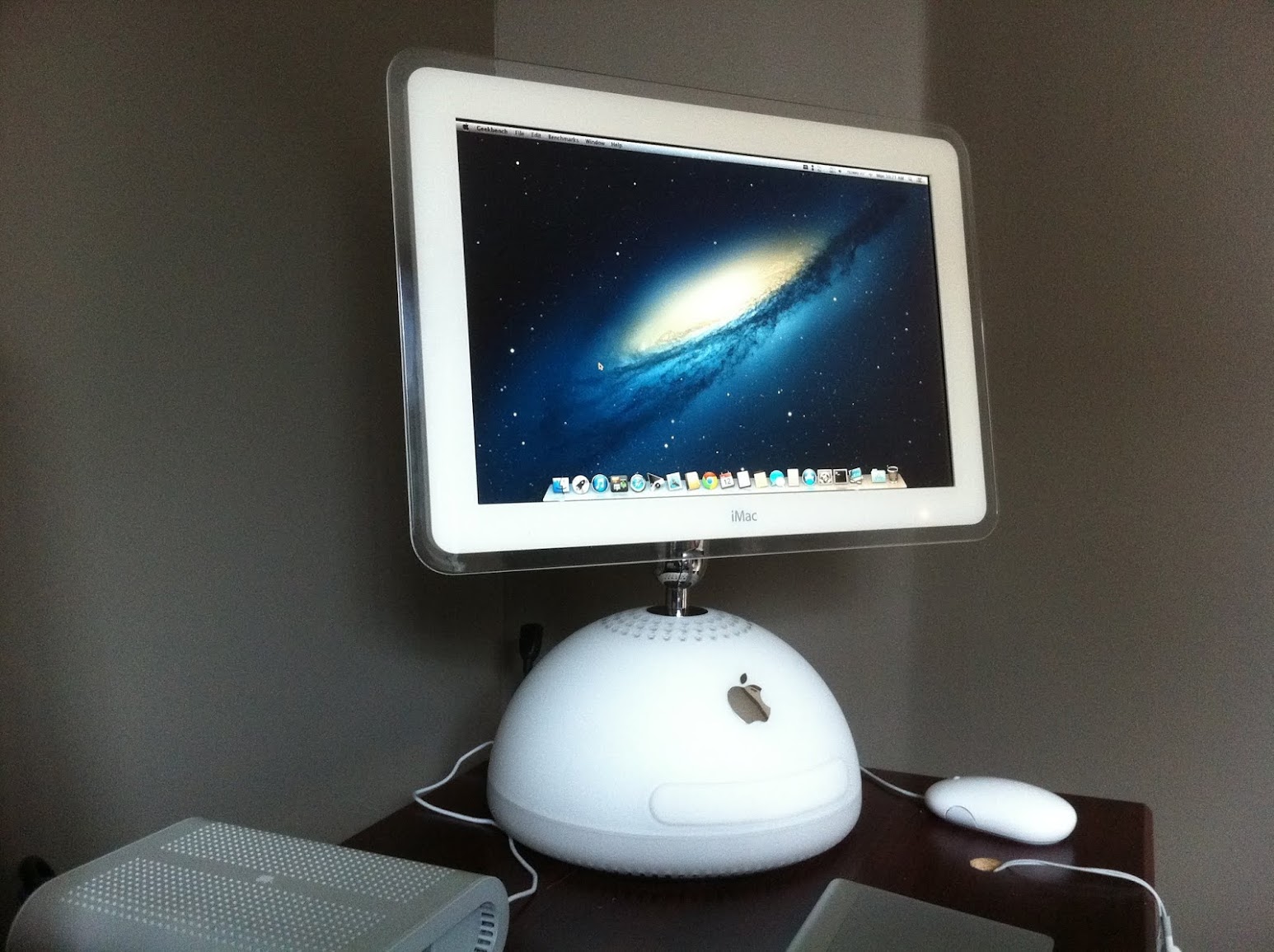
My new iMac G4 17" put together and sitting in it's new home in my office. Its so shiny that there's a reflection of my window at the top edge of the screen.

IMG_4218.JPG


IMG_4222.JPG


Ersterhernd
 
This second iMac G4 has been running flawlessly for a full day. No errors or KP's. Temps are consistent with the first iMac G4, high forties CPU cores at idle. The Noctua 92mm exhaust fan is at 1000rpm (via voltage reducer) and the system is virtually inaudible.


So far so good...


Ersterhernd
 
Brightness Control via Touch Sensors


MacTester if you could have look at this, thanks...

I've installed two touch sensors, one at each end of the DVD door, for decreasing / increasing brightness of the LCD. I've got the Picaxe 08m2 controller running off the 3.3V connect on the PicoPSU. Wiring is nearly identical to yours, the only difference is the violet inverter wire isn't yet connected to ground.

I tested the PWM output with the touch sensors wired to the Picaxe Project board that came with the starter kit. Got all calibrated and working well between 0.7 and 3.15V in nice even increments shown on my voltage meter. I thought I had it beat, until I unplugged the Picaxe chip from the project board and put it into my iMac. The startup brightness is accurate (measured by PWM voltage) when the iMac is booted, but the touch sensor function is not working well at all. The screen does not increase or decrease in a smooth fashion, it flashes (pulses) when the touch sensors are pressed, and there is no difference in the brightness or the measured PWM voltage. I disconnected the orange wire, but got no boot to OSX under about 2V PWM output. Once reconnected, the system will boot right down to 0.7V with a very dim screen, or right up to 3.15V very bright, depending on how the startup PWM output is programmed. From there, it won't move.

I've made some great headway, but am stumped. I see you've set up a calibration interface directly on your Picaxe board. I'm testing my calibration with everything plugged in the iMac except the chip and the 2 sensor wires. I think I've got the calibration close, but still no change in the PWM output, up or down from where the system boots.

Any ideas???


Thx,

Ersterhernd
 
Hmm...

1. The black GND wire from your PSU must be connected to the protection earth on your wall outlet (internal in your PSU, max 3 Ohm resistance).
2. The protection earth must be connected to your faraday cage.
3. The calibration will not work, if it's not done 1:1 with your definitive iMac sensor wiring. That's the reason why I've integrated a serial port in my definitive PCB.

-What are your actual sensor readings for each sensor? (touched / not touched)
-Actual screenshot of your program?
-Photo of your wiring?

Good luck

MacTester
 
Thx for the reply Mactester. The grounds are run from the NUC PSU direct to the grounds (green/yellow to faraday & blue to blue) in the iMac.

Calibration is close, but will require some work to get it right. I'm going to program an auto bright/dim loop tonight that will cycle the LCD from brightest to dimmest up and down without touch sensor input. I want to isolate if this is a PWM issue or a sensor issue. Maybe a faulty 08m2? Who knows.

Troubleshooting is half the fun anyway. It's too easy if it works first try! ;)


Will post more later.


Ersterhernd
 
A setback today. I was adding a small piece of shrink tubing to the naked end of a 3.3V wire to protect from shorting. I didn't unplug the PSU end because I thought a 12" wire would be long enough to isolate the heat from that end. I was proved wrong. While quickly shrinking the tubing with my pencil soldering iron, I heard a pop sound from the picoPSU. As it turned out, the 3.3v rail on the picoPSU was toast. With it went both peripherals connected to 3.3v at the time; my 17" LCD and my a1181 Bluetooth module. It didn't damage the inverter as that was not connected at the time.

Parts are reordered. Ouch, a 150.00 dollar mistake for taking a shortcut not disconnecting wires from the picoPSU before heating the remote end. Damn.


:banghead:


Ersterhernd
 
Oh no, that sucks! Sorry to hear that. :(

my 17" LCD
Does that mean, that your iMac LCD panel was killed?

Good luck with the repair!

MacTester
 
Oh no, that sucks! Sorry to hear that. :(

Does that mean, that your iMac LCD panel was killed?

Good luck with the repair!

MacTester


Yes Mactester, backlights work but no image. Powerbookmedic.com had a grade A replacement in stock. It'll be here in three days. I was going to replace it eventually anyway due to a bright pressure mark.

Live n Learn.


Ersterhernd
 
Took the LCD out last night. It's easy to do, just three 1.5mm hex screws. The replacement is supposed to be here today.


Photo%252520Aug%25252021%25252C%25252006%25252011%25252004.jpeg


Ersterhernd
 
I've just found this statement in the PICAXE manual:

I've built a second pcb (without the download circuit) and the PICAXE program will not
run!

If you program a PICAXE chip in a different board, and then move the chip to a
board without the download circuit, you must ensure that the 'serial in' pin is
tied to ground (0V) on the second board for reliable operation.

This could be the reason, why you have problems with your touch sensors.

MacTester
 
Status
Not open for further replies.
Back
Top