Contribute
Register

Ersterhernds iMac G5 20 Inch A1076 Project

Status
Not open for further replies.
The power switch measures 0 resistance both when pressed and not pressed. I assume I did it wrong then. So to get this right, I need some resistance on 2 holes and when button pressed goes to 0 then correct?
Yeah no such luck with FPH on the laptop. I'm determined though...:problem:

Correct.
 
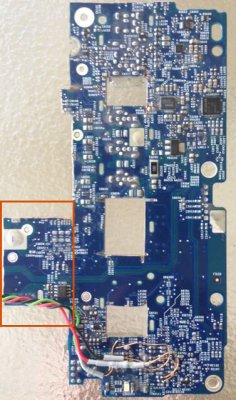
Hi Ersterherd. Thanks for the help. I cannot find a pair of contact holes that gives 0 resistance when button is pressed. I tested most if not all contact points below where the ethernet jack is. I'm not sure now if I can use that power switch. I still hope to still. Maybe I cut too much off? I attached the one in kiwi post. I cut mine straight through the rectangle box. .

Question on another topic. If I split the 20V stand-by to 24V line from the iMac PSU and have one line go to step down regulator having 19V to feed the MB will there be a problem voltage wise on the second going to inverter? I realize that needs to be split as well cause the inverter connector has two 24V lines. If no, will it make a difference where I split the line? The reason I'm running out real-estate fast, and maybe I can just use the main PSU. If not one of the fans probably has to go. Also how in the world did you manage to solder those wires to the HDMI pads. I destroyed the 2 I had, even with a fine tip. Man that is not easy. The second one I tried your other method, using fine solid wire leads. Both ended real bad. You really have 1-2 shots to get a good solder, otherwise it starts to get messy pretty quick. Lucky I found one of these screw in terminal blocks.
 

Attachments

  • IMG_2918.jpg
    IMG_2918.jpg
    77 KB · Views: 192
Last edited:
There was more than one model of G5 logic board used in that era, so the power button connectivity may vary from Kiwis pics. I did three of these builds and encountered 2 different logic board layouts. One of them was a very tiny circular trace that was easily damaged by solder so it was a one shot attempt at a firm connection.

The 20v standby may be very low amperage so you'd have to try it to be sure. My method was bomb proof as the nuc grabbed power from its shipped oem psu. That said, trial and error is the essence of these projects and your ideas may prove successful.

The hdmi conversion is by far the most difficult piece piece of the puzzle. I've made 4 of these cables and had success with all of them. Each took many hours to complete, using the 'helping hand' clamps is vital to succeeding. Soldering skills are definitely tested in this exercise.

Keep going and good luck.

Cheers!
 
Last edited:
Hi Ersterhernds
you have done such an amazing job, so I decided to make my first iMac mod following your project. I have the same model of yours (a1076 20inch). Before making the tmds conversion, I wanted to test the inverter. I connected the two 24v wires, the two GND wires and the 3.3v wire to the corresponding pins of the PSU. To test the backlight I connected the brightness wire to the 3.3v of the PSU, but when I turn the PSU on, the display is still black. The PSU works well because I tested the three fans. My question is, does the lcd light up only with the hdmi cable connected, or there is a problem with my inverter? (it worked before I started the mod) Sorry for the possible stupid question, but I'm a newbie and I'm trying to learn more :)
Thank you in advance
 
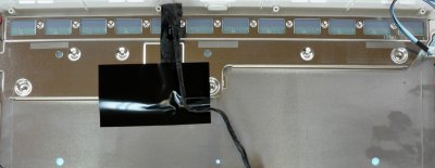
Did you check the holes on the back of the LCD panel for the operation of the back lights ?

The panel is actually very dim without an image on it. I tested mine the same way as you but had to view the functioning back lights though the holes at the rear.

Cheers!
 
I looked at the lcd panel from the front side and I didn't saw any light. I'll check as soon as possible because I'm not at home. Do you mean the holes that I find lifting the midplane? I attached an image found online to be sure I understood.
Thanks
 

Attachments

  • lcd.jpg
    lcd.jpg
    151.9 KB · Views: 165
Hi Ersterhernd. Thanks for the replies. I trust your expertize here since you have done this a few times. This is my first. Yes, it seems every board is unique. Mine is not the same as the one pictured as well. Is there some procedure on how to trace? Does it have to be in that corner, or can the contacts be anywhere in the board?

My approach due to space is to utilize just the existing PSU for now. I will tap into the 20V standby, go to a step down, then come out with a DC pin barrel connector 19.5V for MB. Reason for step down is of course is 24V when on. Will see how the amps works. I figure the MB has no battery or screen to feed so demand should be low. I will steal a 3V or 5V line from one of the ribbon cables connected to MB. I do have a 5V and 3.3V either from LED lighting header board, or touchpad connector cable. That will go to the relay and jump start the PSU. They are off until you power up.

A couple things: The inverter connector has 2 pins of 24V. Did you split the line in 2 and connect both pins?
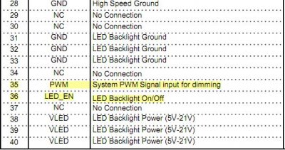
Regarding brightness, what happens if I steal a 3.3V line from the LVDS connector? Pin 2,3,4 are all 3.3V from the 40pin connector. Do one of these control the screen brightness? I cannot find any literature what pin is responsible on the 40 pin cable, if it does come from that connector? Your take on this idea?
Things are starring to get tight in that case.:problem:
 
I hope your idea of the 24v step-down works. That'd be great.

Yes just split the 24v line and ground line into 2 at the inverter. Carefully label the lines while they are still seated in the Apple connector as they're all black and can be easily confused once removed.

For brightness I would take both your 3.3v lines directly from the imac psu. One will need to be put through a potentiometer as the full 3.3 will be far too bright. You'll need to formulate some kind of adjustment method as I had to.

Yes, It'll be a very full case when complete.

Cheers!
 
Last edited:
For brightness I would take both your 3.3v lines directly from the imac psu. One will need to be put through a potentiometer as the full 3.3 will be far too bright. You'll need to formulate some kind of adjustment method as I had to.

Yes, potentiometer will be last resort. Brightness control is the next obstacle. Wow this is been one challenging adventure. Have a look at the attached pic. I found a pin out online. Will that be useful for me if I can tap into pin 35 and 36? I'm confused with this PWM line. Is that that adjustable voltage line?
 

Attachments

  • lvds connector.jpeg
    lvds connector.jpeg
    57 KB · Views: 459
Status
Not open for further replies.
Back
Top