- Joined
- May 27, 2010
- Messages
- 2,364
- Motherboard
- Dell Optiplex 9030 All in One
- CPU
- i5-4690K
- Graphics
- HD 4600
- Mac
- Classic Mac
- Mobile Phone
Clear G4 Cube - Passive cooled (sort of!)

This post has been re-done today - 22 January 2012.
This project was done for a few reasons:
(1) It was a long time since I had tried to put a motherboard in a Cube and that time it was a real Mac - old Mac Mini - that got the treatment
(2) I had a laser cutter just about to arrive for part of a new business and wanted to get some experience designing and cutting different materials.
(3) I was bored with my Zotac sitting in a Silverstone case and....
(4) Most importantly I was inspired by the stuff going on in this forum with Cubes from 61mg73, NeilHart and EelHead and fancied putting a different twist on the project.
It started with this:

[I thought at the BIN price of £60 (since I had just seen an average but empty case sell for £46 at auction) I didn't really have much to lose as the power supply is worth £50 if it works (it does!) and I have a couple of old graphics cards from dead cubes lying around.]
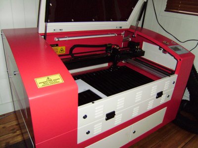
and this my long awaited toy business venture:
The laser.JPG
From the start I was also interested to see if I can either make use of the passive cooling that the Cube had - I wanted it to do more than just take up just take up tonnes of room.
I thought about keeping the Cube power supply as it would have made the perfect partner for this: http://linitx.com/product/12004

It'd be quite cool to use an original Cube silent power brick to power a re-incarnation of it and that internal board looks like it might be able to throw out a bit more welly than one of the picopsus.
In the end though as I already had a Pico PSU and an adapter in my power supply I decided to use that.
First stage was to get designing and in the beginning I made up a template for a Mini-ITX motherboard tray and a few other bits and pieces and just did a try out:

Loved the dramatic lighting on that! This first cut on my machine was pretty satisfying and the 5mm acrylic came out really well - though it was too skinny at the left edge of the I/O plate and I felt was not up for the rigours of being pushed around inside the Cube.
Here are a few pic.s of the first version where I put the board in to the cube with my new custom backplate and working handle:


About this time I also realised just how tight things were in the cube - mounting a mini-ITX where the Cube mobo went is not feasible if you want to keep the touch switch. The front of the board interferes with it.
That means you have to re-jig things and I went for mounting the mobo where the hard drives were in the original cube as that gave some more headroom too.
However....mounting down there means the mobo front interferes with the latching mechanism for the handle:

Here the front RAM slot is blocked by the case latch and the picopsu is shoved hard against the end of the case straining the MOBO. Not good.
So I took a couple of decisions on this build (as I had now definitely decided that I was going to make the Zotac fit - incidentally the Intel thin ITX board I think would have none of these problems!!). First, the Pico PSU would be relocated as just a few mms make a difference, and second I would rethink the whole heatsink and handle thing.
I don't sleep a lot at nights, but one of the benefits is that I end up designing stuff in my head to occupy the time. The result of a sleepless night was how to passively cool the Cube, cure the space issues, have a removable core (save the world, cure cancer...).
I decided to have a different take on the old Powerlogix enclosure, which looked like this:
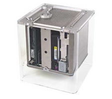
The Powerlogix did away with the inner case and made it all see through. It also had a different top design and more space to get more air in.
The passive cooling I went for originally had been intended to be heatpipe based, but when I saw the size of the pipes and all the hardware a different solution came to mind - why not just turn the heatsink over, and close the gap between the processor and the flat face of the heatsink with a block of conductive aluminium.
So:


The above images show the hardware I used to do the attachment to the heatsink - the processor block was a 4cm cube of aluminium from HFX with acrylic spring to attach to the motherboard and CPU with correct force. The other block was home made and used to bridge the gap between the HFX heatsink and the Cube heatsink. This upper block bolts onto the HFX one below it and then up to the heatsink above it.
In my final version, instead of the heatsink being absolutely fixed in one position I made a sliding linkage at the back of my new acrylic panel that allowed the heatsink to be raised (or lowered) by a few mm's and then be fixed in place. I did that to make sure that the weight of the heatsink did not bear down upon the processor or Mobo.
(Will post some pic.s of this linkage here later).
When I tested this out with some video encoding and benchmarking and no other cooling the CPU coped very well but temp.s climbed to a max in the low 70 C's. While that was coped with well and was truely silent I decided that for a better life expectancy I should add a bit of airflow - so I used the same principle Apple had planned for more powerful Cubes (sadly never produced!) and added a base fan. However, as I had lots of room I could add a Noctua 92mm fan and have it on slow ultra low noise speed - incredibly this single change brought about a 25 degree drop in temp across the whole operating range!!!! And it is still silent (unless you put your ear to it).

Having decided I wanted to avoid the problems with the handle and go the powerlogix style I ditched the handle and was able to use the space where the handle was to route a ATX extension cable meaning I could mount the PicoPSU somewhere else.


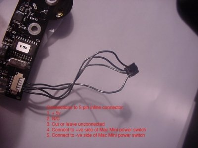
I had already figured out how to wire up the Cube proximity switch a few years ago and wrote an online guide to it, here is a pic from it:
Cube Switch.jpg
Basically, the picture says how to do it. You must use the 5Vstandby voltage from the PSU, you must keep to the polarity of the power switch mentioned and the three connections labelled by me as 1,4 and 5 (for Mac Mini switch just substitute Power_sw outputs from mobo) are all you need to get the switch working. The trick to get the LED working as a power LED indicator is to use the light green power_on signal from the mobo and connect that via a suitable resistor to the LED on the cube switch like I show here:


Though the two pic.s here are not very clear, basically what I am doing is soldering a wire to the cathode of the led (the leg closest to the large central gap in the metal cube top plate), connecting that to a resistor of around 500 Ohms and then connecting the other side of that resistor to the Power_On light green wire. In the pic.s I do that by actually soldering the end of the resistor to the unused terminal "2" of the switch board so I can use the plug from that connector for all my switch connections.
This way of connecting means you get the LED to glow all the time the Cube is on and you get it to glow more strongly when it senses your finger near it....cool eh?
So finally, I come to the finished (well nearly) product.
These last photos show what I did today. The top of my old cube enclosure has been lasered off (actually things got a bit messy and tense for a while doing that!), and a new top lasered. I also made a plastic mesh cover - which i will be replacing with a lasered blue mirrored plate - and used some old handles I have.


So, that's pretty much it. Hope you like it.
As you can see, it works in the case and outside of it too. I think it is different in many ways to other mod.s - pretty much silent like the original, cool (cruises at 30 degrees) and being removeable from the top of the enclosure makes it more versatile than the powerlogix enclosure which had to have nuts and bolts unscrewed.
Be happy for your comments!
This post has been re-done today - 22 January 2012.
This project was done for a few reasons:
(1) It was a long time since I had tried to put a motherboard in a Cube and that time it was a real Mac - old Mac Mini - that got the treatment
(2) I had a laser cutter just about to arrive for part of a new business and wanted to get some experience designing and cutting different materials.
(3) I was bored with my Zotac sitting in a Silverstone case and....
(4) Most importantly I was inspired by the stuff going on in this forum with Cubes from 61mg73, NeilHart and EelHead and fancied putting a different twist on the project.
It started with this:
[I thought at the BIN price of £60 (since I had just seen an average but empty case sell for £46 at auction) I didn't really have much to lose as the power supply is worth £50 if it works (it does!) and I have a couple of old graphics cards from dead cubes lying around.]
and this my long awaited toy business venture:
The laser.JPG
From the start I was also interested to see if I can either make use of the passive cooling that the Cube had - I wanted it to do more than just take up just take up tonnes of room.
I thought about keeping the Cube power supply as it would have made the perfect partner for this: http://linitx.com/product/12004
It'd be quite cool to use an original Cube silent power brick to power a re-incarnation of it and that internal board looks like it might be able to throw out a bit more welly than one of the picopsus.
In the end though as I already had a Pico PSU and an adapter in my power supply I decided to use that.
First stage was to get designing and in the beginning I made up a template for a Mini-ITX motherboard tray and a few other bits and pieces and just did a try out:
Loved the dramatic lighting on that! This first cut on my machine was pretty satisfying and the 5mm acrylic came out really well - though it was too skinny at the left edge of the I/O plate and I felt was not up for the rigours of being pushed around inside the Cube.
Here are a few pic.s of the first version where I put the board in to the cube with my new custom backplate and working handle:
About this time I also realised just how tight things were in the cube - mounting a mini-ITX where the Cube mobo went is not feasible if you want to keep the touch switch. The front of the board interferes with it.
That means you have to re-jig things and I went for mounting the mobo where the hard drives were in the original cube as that gave some more headroom too.
However....mounting down there means the mobo front interferes with the latching mechanism for the handle:
Here the front RAM slot is blocked by the case latch and the picopsu is shoved hard against the end of the case straining the MOBO. Not good.
So I took a couple of decisions on this build (as I had now definitely decided that I was going to make the Zotac fit - incidentally the Intel thin ITX board I think would have none of these problems!!). First, the Pico PSU would be relocated as just a few mms make a difference, and second I would rethink the whole heatsink and handle thing.
I don't sleep a lot at nights, but one of the benefits is that I end up designing stuff in my head to occupy the time. The result of a sleepless night was how to passively cool the Cube, cure the space issues, have a removable core (save the world, cure cancer...).
I decided to have a different take on the old Powerlogix enclosure, which looked like this:
The Powerlogix did away with the inner case and made it all see through. It also had a different top design and more space to get more air in.
The passive cooling I went for originally had been intended to be heatpipe based, but when I saw the size of the pipes and all the hardware a different solution came to mind - why not just turn the heatsink over, and close the gap between the processor and the flat face of the heatsink with a block of conductive aluminium.
So:
The above images show the hardware I used to do the attachment to the heatsink - the processor block was a 4cm cube of aluminium from HFX with acrylic spring to attach to the motherboard and CPU with correct force. The other block was home made and used to bridge the gap between the HFX heatsink and the Cube heatsink. This upper block bolts onto the HFX one below it and then up to the heatsink above it.
In my final version, instead of the heatsink being absolutely fixed in one position I made a sliding linkage at the back of my new acrylic panel that allowed the heatsink to be raised (or lowered) by a few mm's and then be fixed in place. I did that to make sure that the weight of the heatsink did not bear down upon the processor or Mobo.
(Will post some pic.s of this linkage here later).
When I tested this out with some video encoding and benchmarking and no other cooling the CPU coped very well but temp.s climbed to a max in the low 70 C's. While that was coped with well and was truely silent I decided that for a better life expectancy I should add a bit of airflow - so I used the same principle Apple had planned for more powerful Cubes (sadly never produced!) and added a base fan. However, as I had lots of room I could add a Noctua 92mm fan and have it on slow ultra low noise speed - incredibly this single change brought about a 25 degree drop in temp across the whole operating range!!!! And it is still silent (unless you put your ear to it).
Having decided I wanted to avoid the problems with the handle and go the powerlogix style I ditched the handle and was able to use the space where the handle was to route a ATX extension cable meaning I could mount the PicoPSU somewhere else.
I had already figured out how to wire up the Cube proximity switch a few years ago and wrote an online guide to it, here is a pic from it:
Cube Switch.jpg
Basically, the picture says how to do it. You must use the 5Vstandby voltage from the PSU, you must keep to the polarity of the power switch mentioned and the three connections labelled by me as 1,4 and 5 (for Mac Mini switch just substitute Power_sw outputs from mobo) are all you need to get the switch working. The trick to get the LED working as a power LED indicator is to use the light green power_on signal from the mobo and connect that via a suitable resistor to the LED on the cube switch like I show here:
Though the two pic.s here are not very clear, basically what I am doing is soldering a wire to the cathode of the led (the leg closest to the large central gap in the metal cube top plate), connecting that to a resistor of around 500 Ohms and then connecting the other side of that resistor to the Power_On light green wire. In the pic.s I do that by actually soldering the end of the resistor to the unused terminal "2" of the switch board so I can use the plug from that connector for all my switch connections.
This way of connecting means you get the LED to glow all the time the Cube is on and you get it to glow more strongly when it senses your finger near it....cool eh?
So finally, I come to the finished (well nearly) product.
These last photos show what I did today. The top of my old cube enclosure has been lasered off (actually things got a bit messy and tense for a while doing that!), and a new top lasered. I also made a plastic mesh cover - which i will be replacing with a lasered blue mirrored plate - and used some old handles I have.
So, that's pretty much it. Hope you like it.
As you can see, it works in the case and outside of it too. I think it is different in many ways to other mod.s - pretty much silent like the original, cool (cruises at 30 degrees) and being removeable from the top of the enclosure makes it more versatile than the powerlogix enclosure which had to have nuts and bolts unscrewed.
Be happy for your comments!