Contribute
Register

Project: Quicksilver Power Mac i7

Status
Not open for further replies.
Joined
Dec 9, 2010
Messages
29
Motherboard
iMac 27" (Late 2012)
CPU
Intel Core i7 3770 @ 3.4GHz
Graphics
GeForce GTX 680MX
Mac
  1. iMac
  2. MacBook Air
Classic Mac
  1. 512K
  2. Apple
  3. Classic
  4. iMac
  5. Power Mac
  6. PowerBook
  7. Quadra
  8. SE
Mobile Phone
  1. iOS
Hey all,

I'm in the process of working on my Power Mac G4 Quicksilver case conversion for my main desktop rig, and I wanted to share my progress and work here. I've been inspired by a lot of the really great G5/Mac Pro mods on this forum, but I wanted to do something different and I personally prefer the older G4 case design to the newer Mac towers. Aside from that, there are very few G3/G4 chassis conversions out there, and even fewer still that didn't make me cringe at the hackery! (more on that later)

Having been a Mac user for life (the first Mac in the house was an SE running System 6) there were plenty of old Macs floating around the house to choose from. I got to eyeing my Power Mac G4 Cube, and thinking that I could pick up an empty Cube on eBay and fit it with a mini-ITX board. Unfortunately, that would require replacing my 1366 processor and almost every other component, so I quickly decided that I needed to use a case that could accommodate a micro-ATX board that would be able to use my existing CPU, RAM, and video card. I had settled on a Sawtooth G4, but that changed when my boss happened to give me the Quicksilver with a dead logic board while I was still in the planning stages! The Quicksilver was a perfect choice for me because it is still modern and sleek enough looking after all these years and the silver color scheme still nicely matches modern Apple keyboards/mice/displays. Moreover, I am a fan of small computers, and the G4 towers are about as compact as you can make a non-ITX system and are no bigger than the Antec Super LanBoy which currently houses my Hackintosh (something that can definitely not be said for the G5/Mac Pro). And so, the ultimate Power Mac G4 upgrade was started... a project I like to refer to as the Power Mac i7.

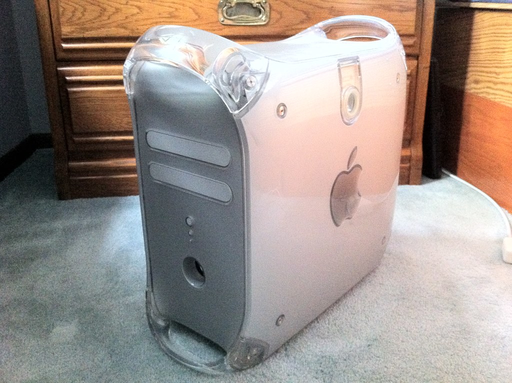
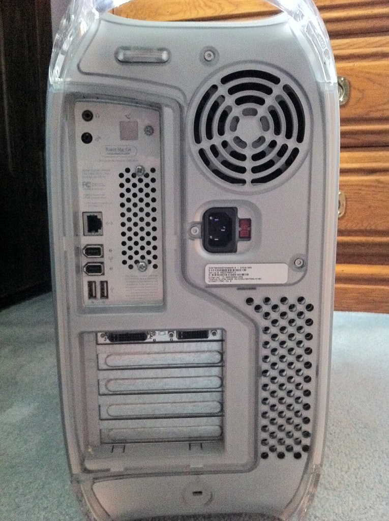
The G4 Quicksilver before starting the project:

7753180888_ca0ff70b1b_b.jpg


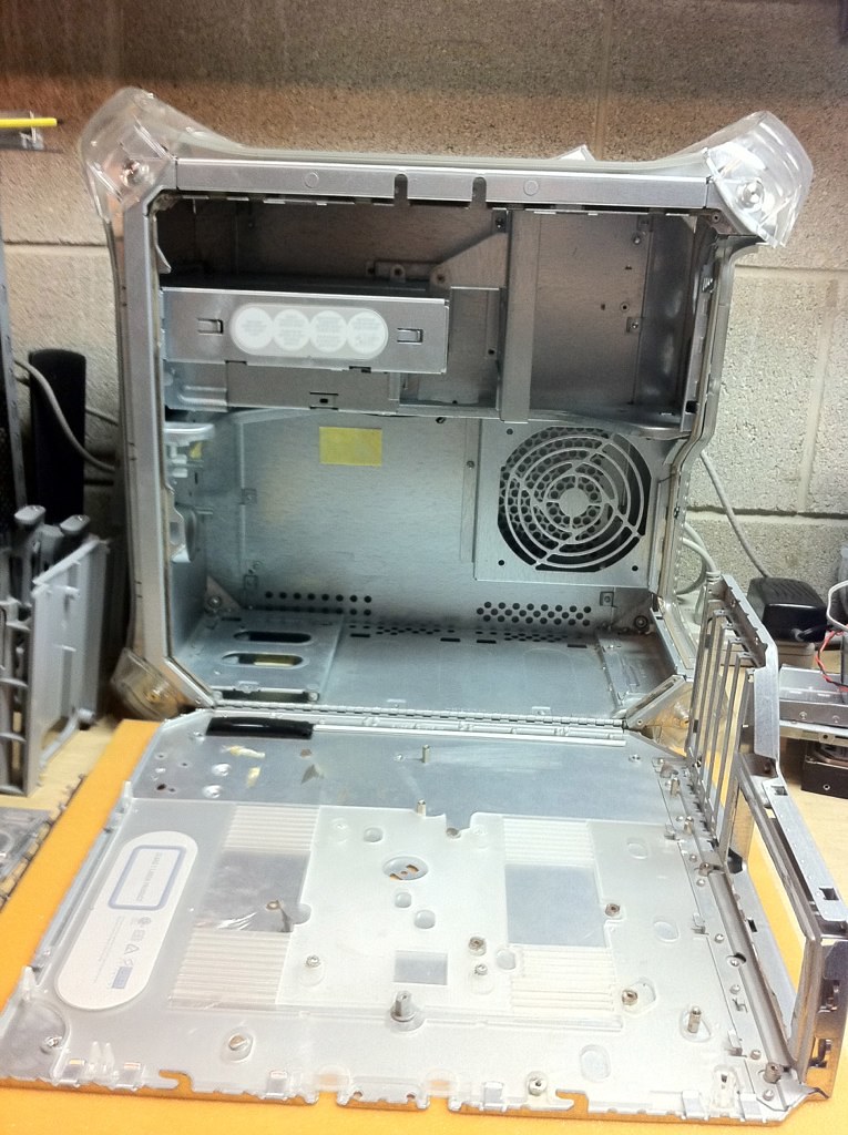
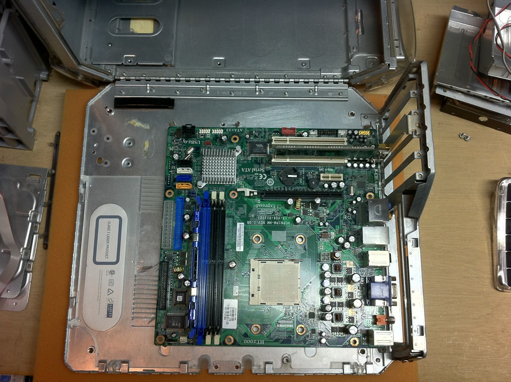
One of my favorite features has always been the fold-down motherboard door. It makes upgrading and tinkering, both of which I do frequently, an absolute breeze. Plus, it's just slick. :cool:

7753183116_915b9fbf57_b.jpg


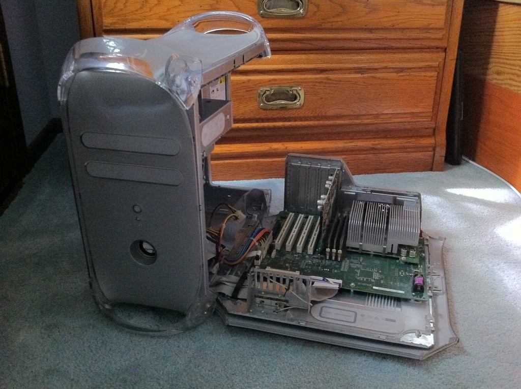
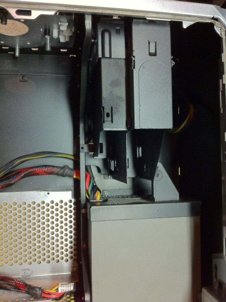
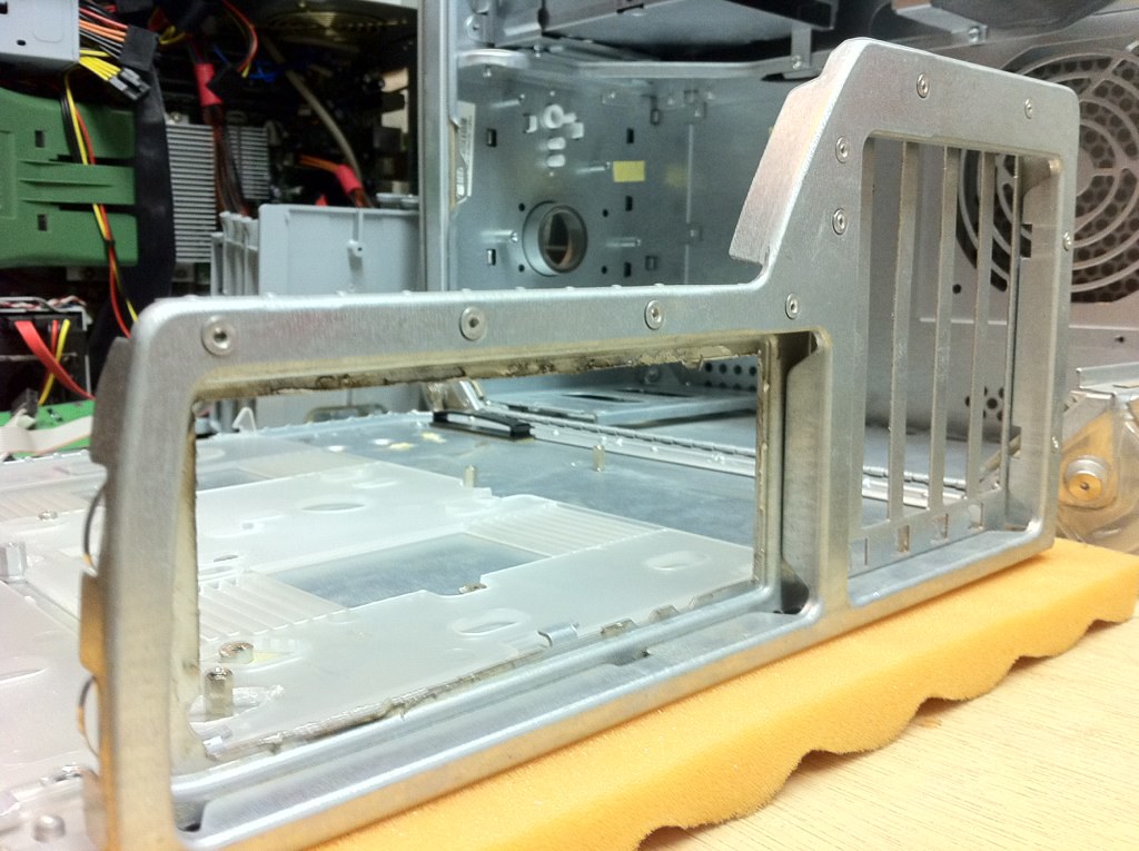
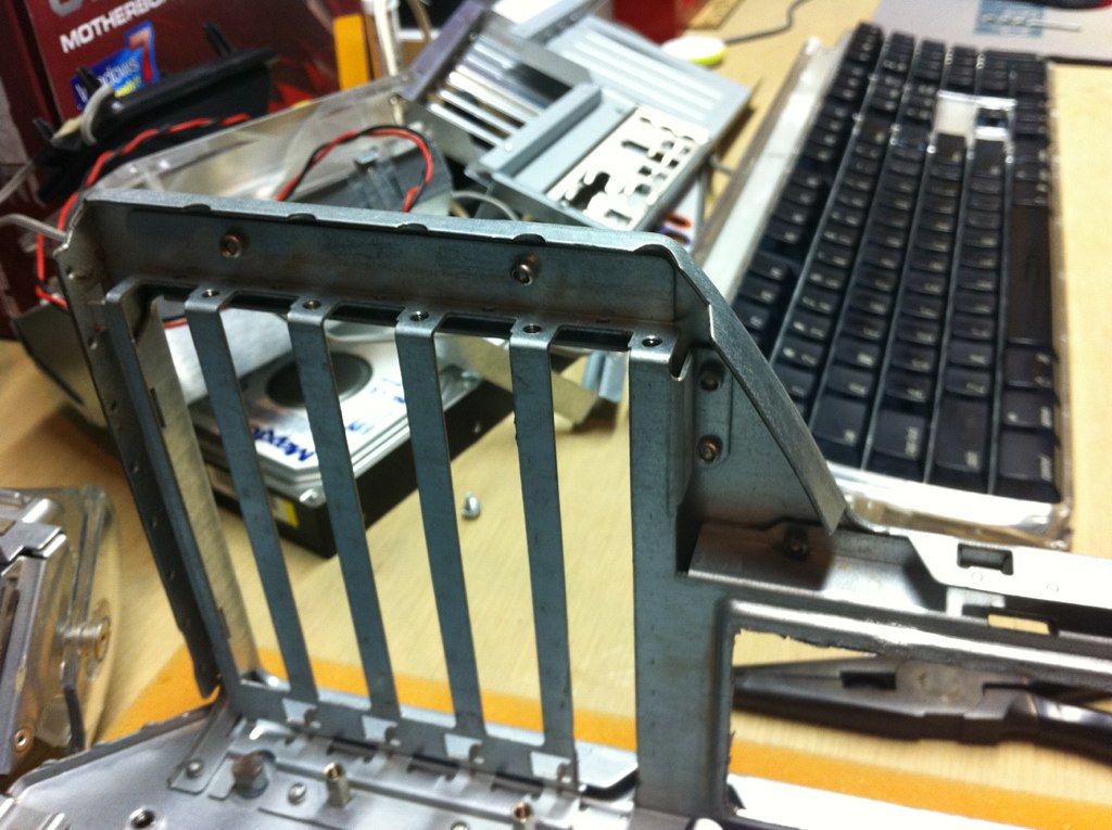
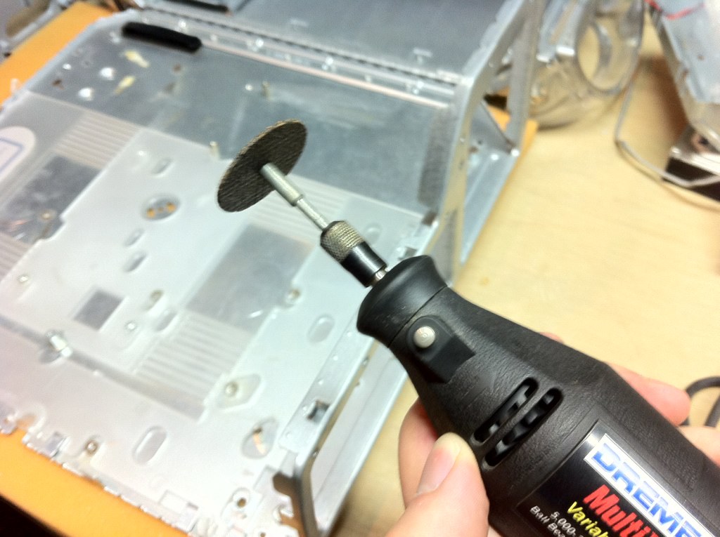
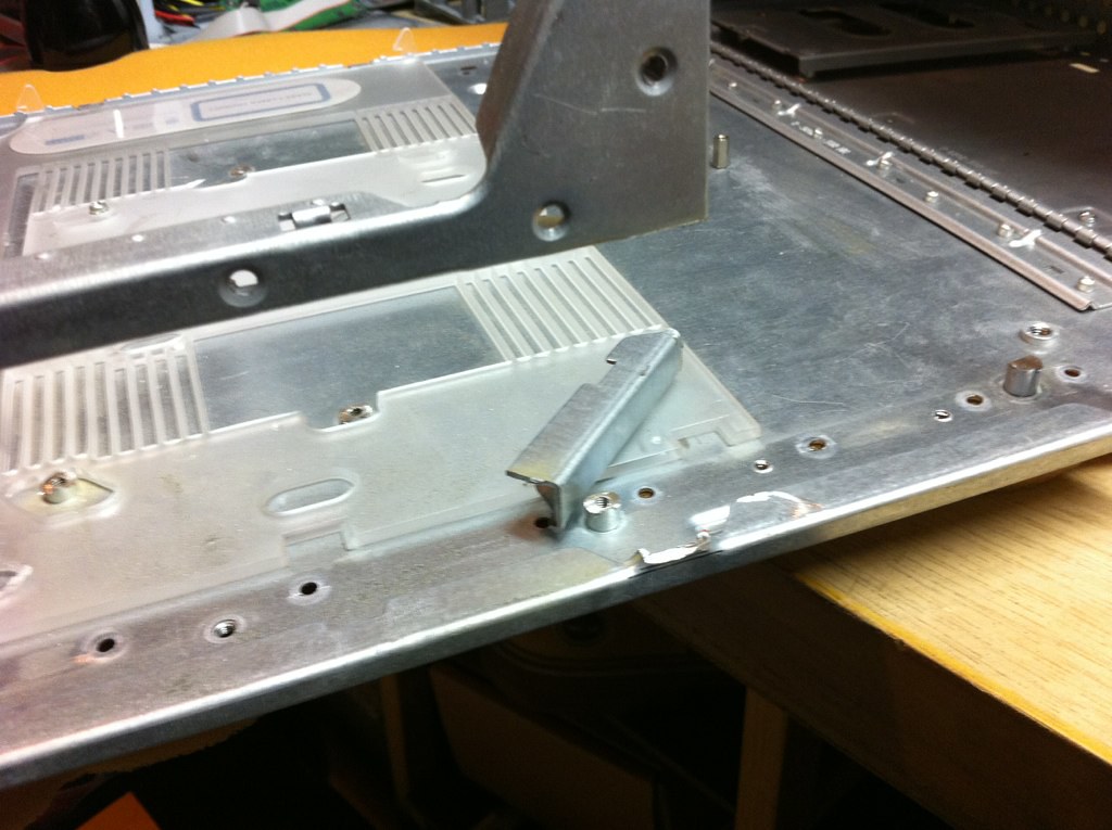
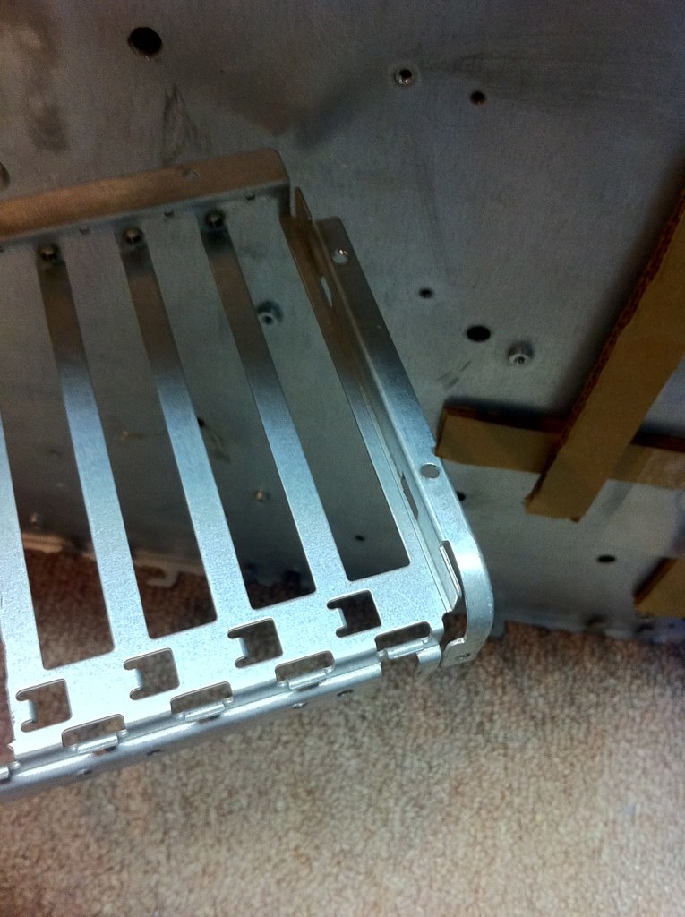
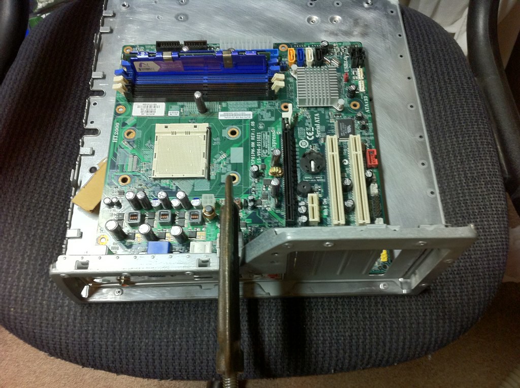
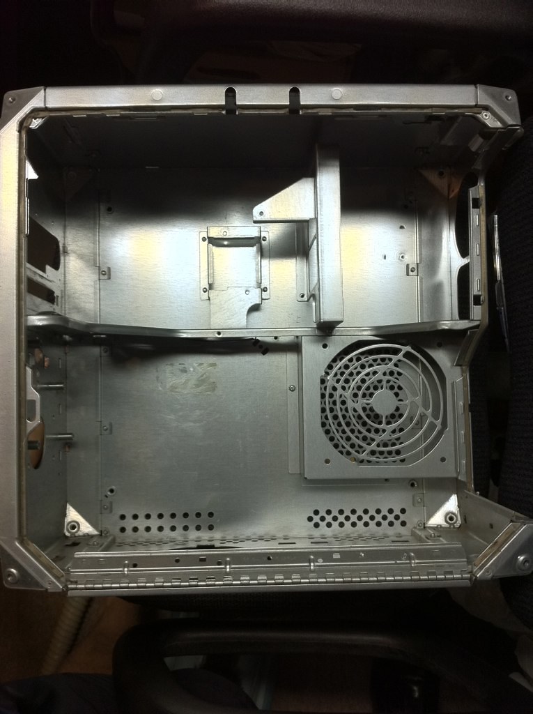
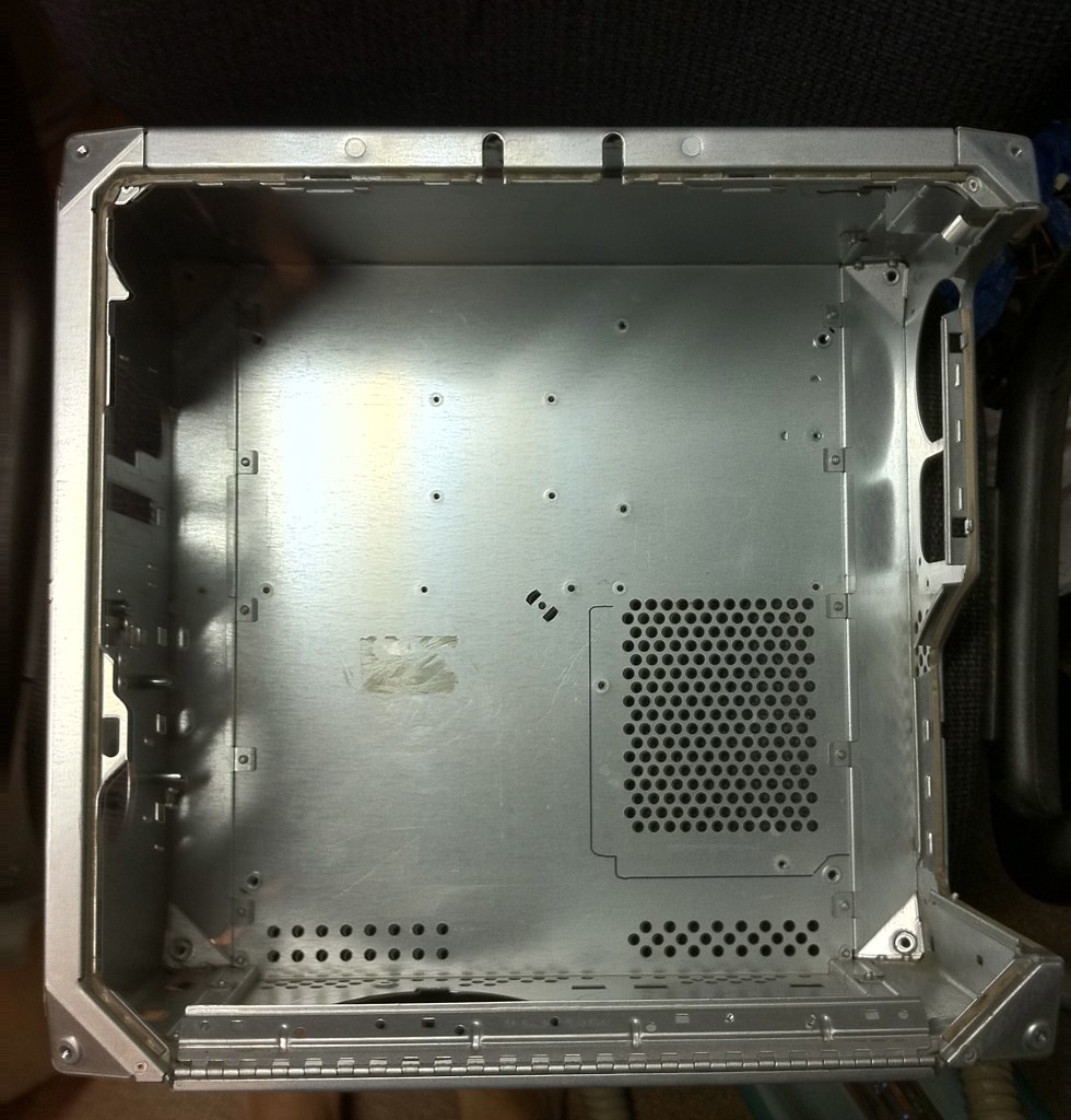
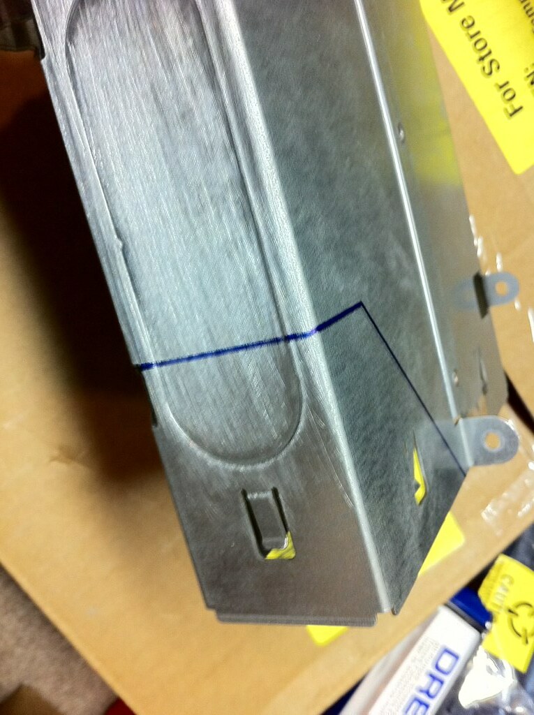
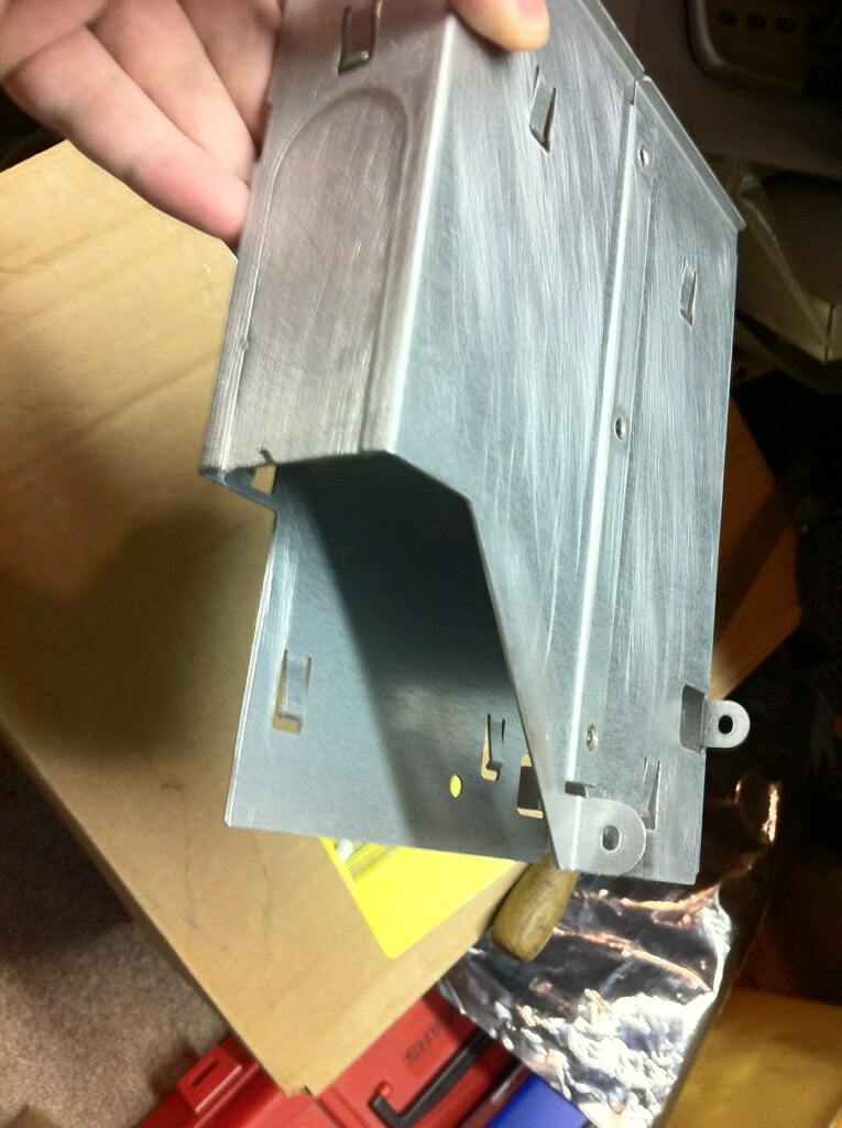
The biggest problem with using this case, airflow issues aside, is the optical drive bay. Because of the position of the memory slots on a standard ATX or mATX board, they hit the optical drive carrier and prevent the door from coming even close to closing. The original Apple board was conveniently laid out to avoid this issue, but we have no such luxury with off-the-shelf parts! The optical drive carrier would literally have to be about half the length it is now, and nobody makes a standard drive of that length. This particular pesky issue actually caused me to abandon a project like this six or seven years ago without even starting, but I have some ideas to bypass it now. ;)

7753181914_72bce83827_b.jpg


7753182480_98a1668e0a_b.jpg


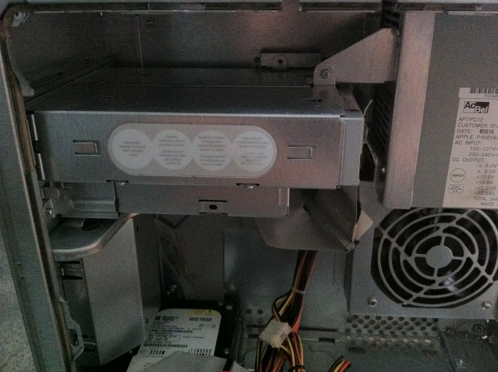
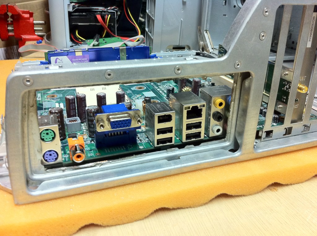
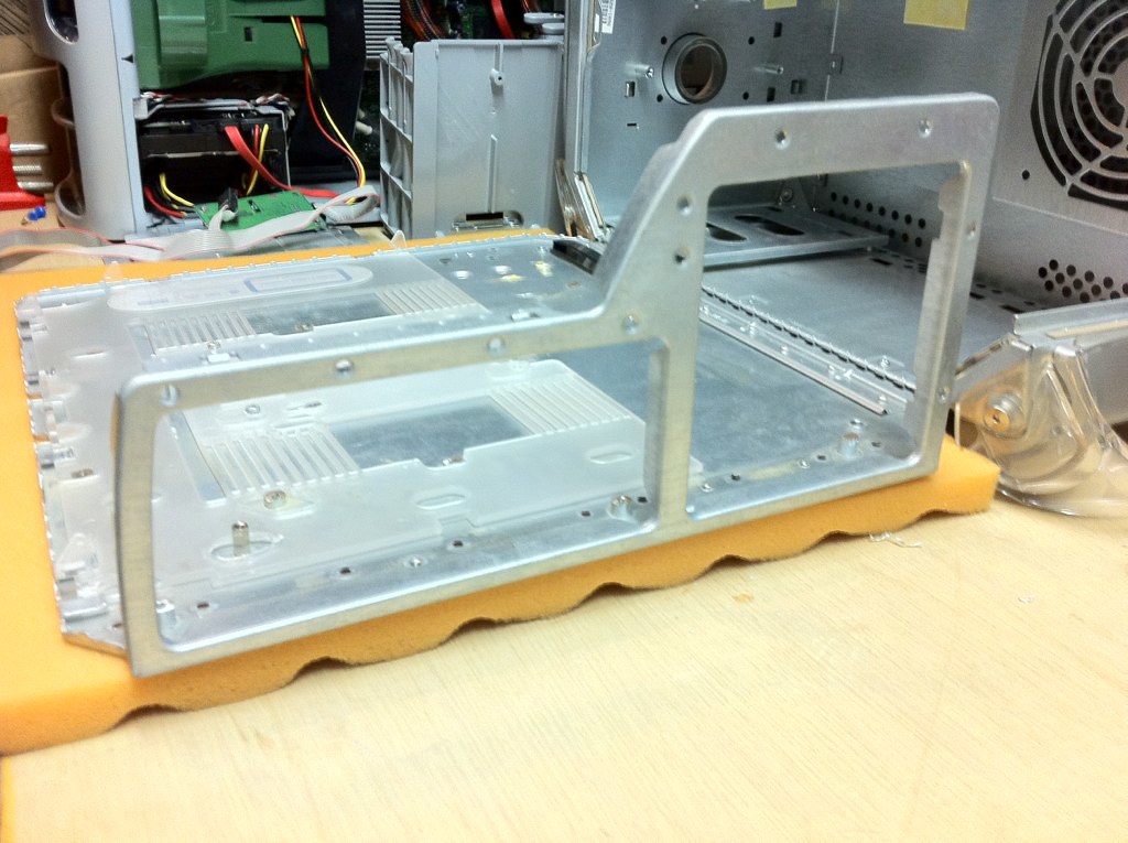
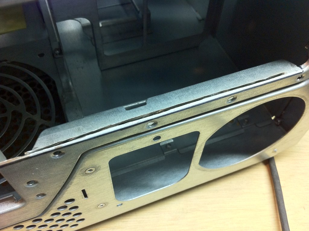
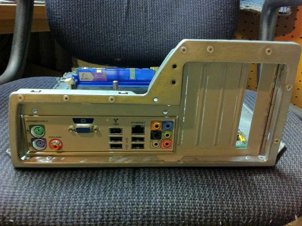
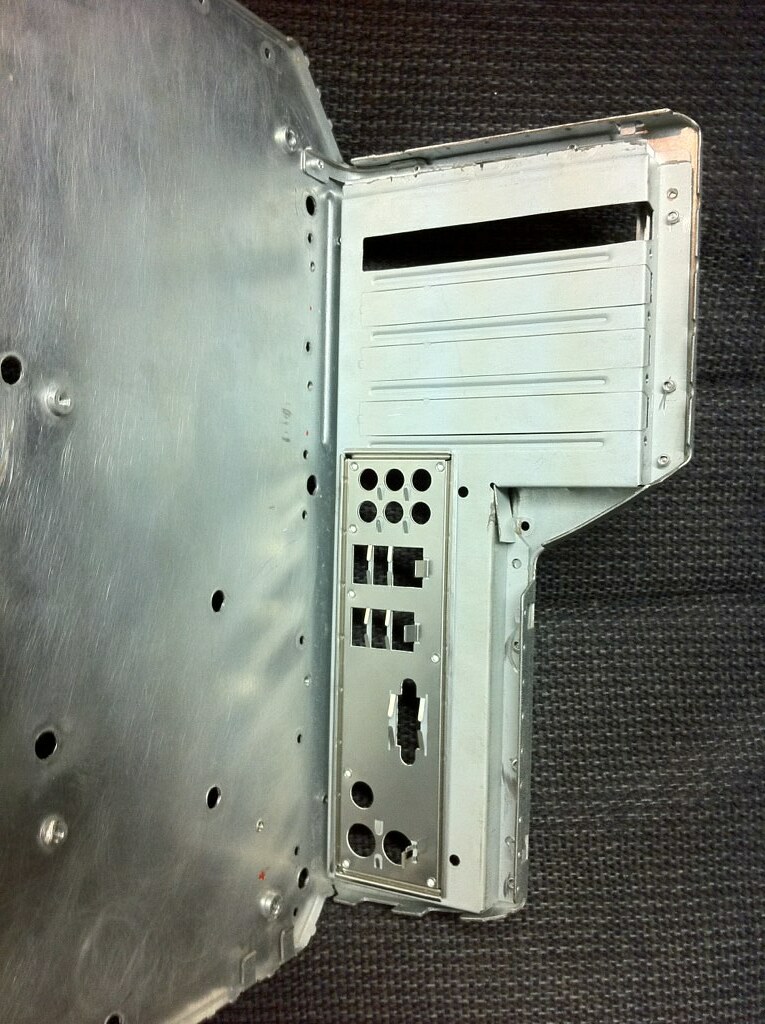
The back of the computer also poses a couple of issues. For one thing, the spacing between the I/O ports and the expansions slots is way too large for a mATX board. Most of the other G4 mods I have seen skate this issue by just accepting that the thick plastic pillar will block the audio ports and adding a PCI audio card, or making ugly cuts to the plastic/metal. Naturally, these are compromises that I won't accept! The other problem is the power supply. The original part is basically an ATX PSU with some of the pins switched (thanks, Apple) so mounting it is not a problem, but finding a modern one that lines up with the fan and socket openings on the plastic is a bit of a challenge. Most modern PSUs have just a single 120mm fan on the bottom rather than a rear 80mm, and with the mounting orientation in this case, that big fan would be pressed up against the side of the chassis which would cause all sorts of problems. Fortunately, I managed to find a suitable PSU with the features that I wanted. In order to keep the mod as Apple stock as possible in appearance, it's important to me to retain as much of the original back plastic as possible rather than having the bare chassis back here, which would no doubt make things easier.

7753181412_21fa48e2e4_b.jpg


Build Specs:
  • Intel Core i7 970 - 6 Cores @ 3.2GHz (LGA 1366)[/*:m:3kxx5qh6]
  • ASUS Rampage II GENE (The GENE is necessary to fit the mATX requirement of the G4 case)[/*:m:3kxx5qh6]
  • 24GB (6x4GB) Corsair Vengeance[/*:m:3kxx5qh6]
  • XFX Radeon 5770[/*:m:3kxx5qh6]
  • 2x160GB Intel 320-series SSD in RAID 0 as boot drive[/*:m:3kxx5qh6]
  • 2x1TB Seagate Barracuda for storage[/*:m:3kxx5qh6]
  • Of course, Mac OS X Mountain Lion[/*:m:3kxx5qh6]

Project Objectives:
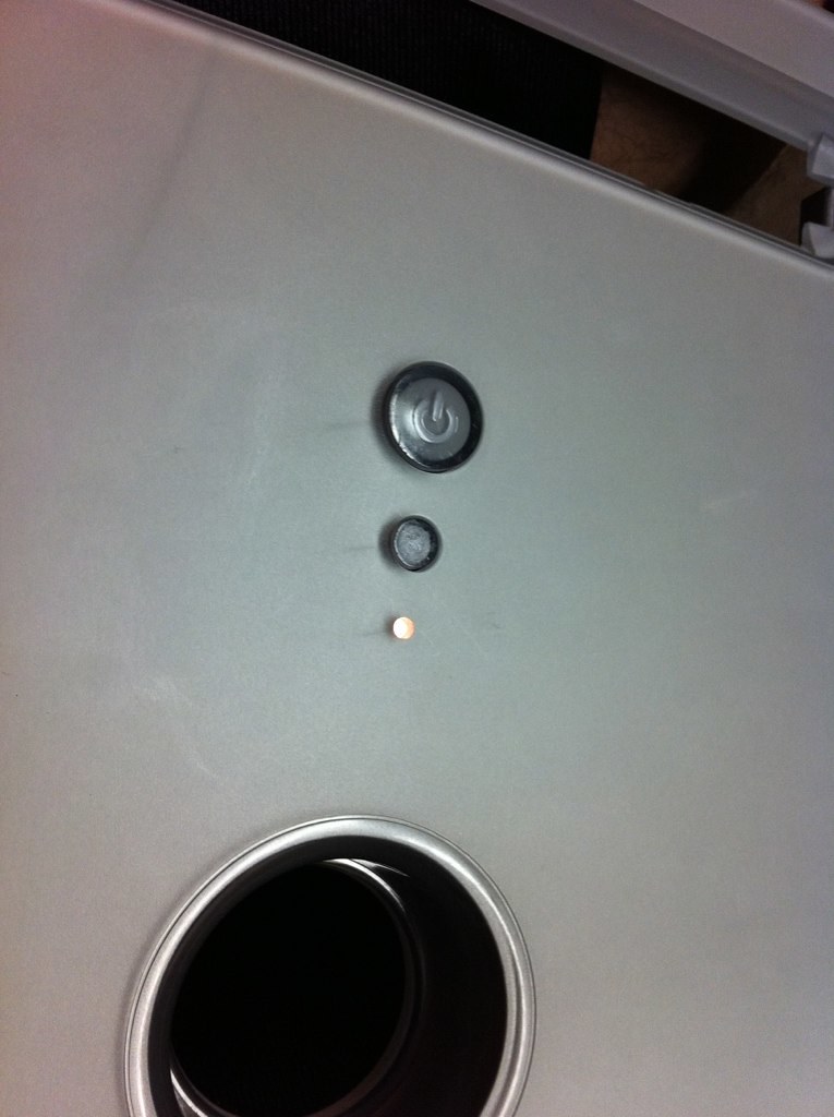
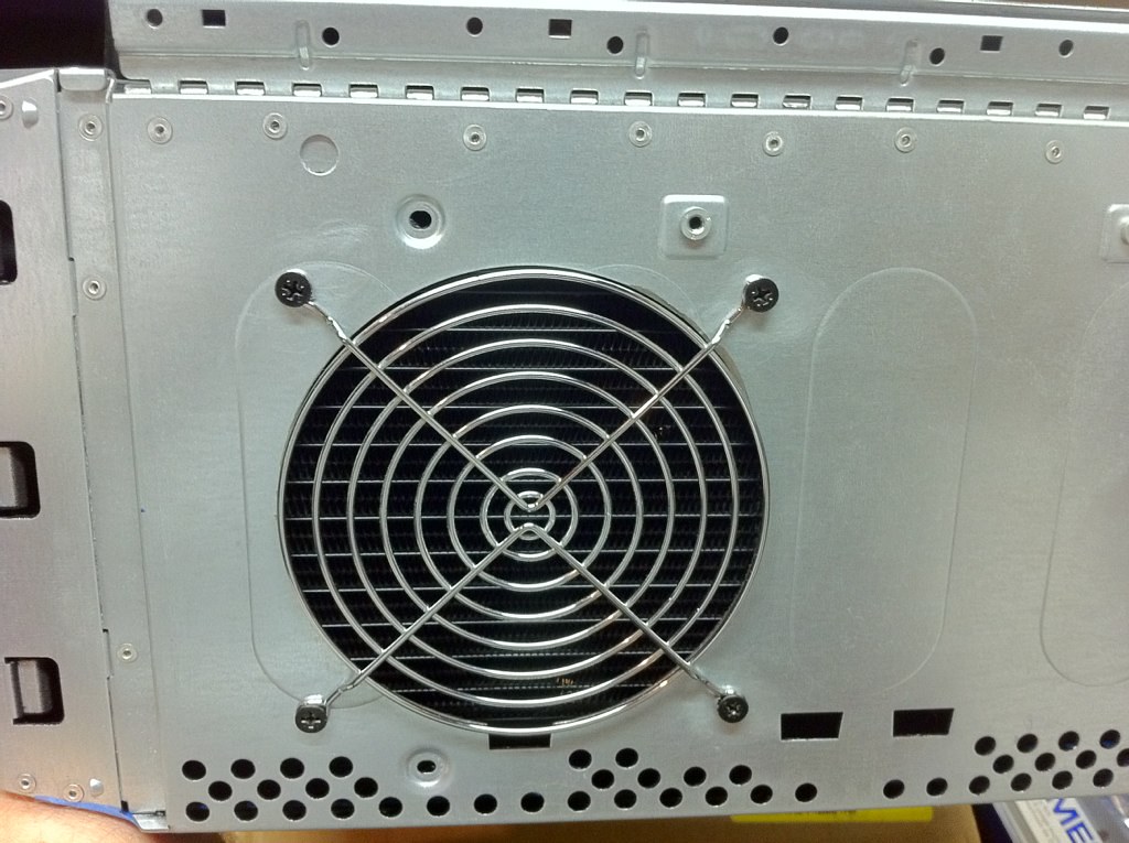
  • Case must appear stock from the outside. This was my biggest disappointment when researching previous G4 case mods... all but a couple that I saw look like total hackjobs. The back panels usually look sloppy, and almost all of them cut blowholes into the top of the case.[/*:m:3kxx5qh6]
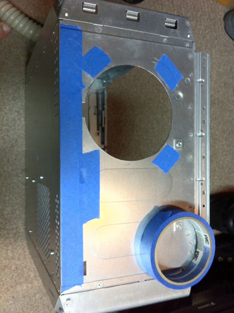
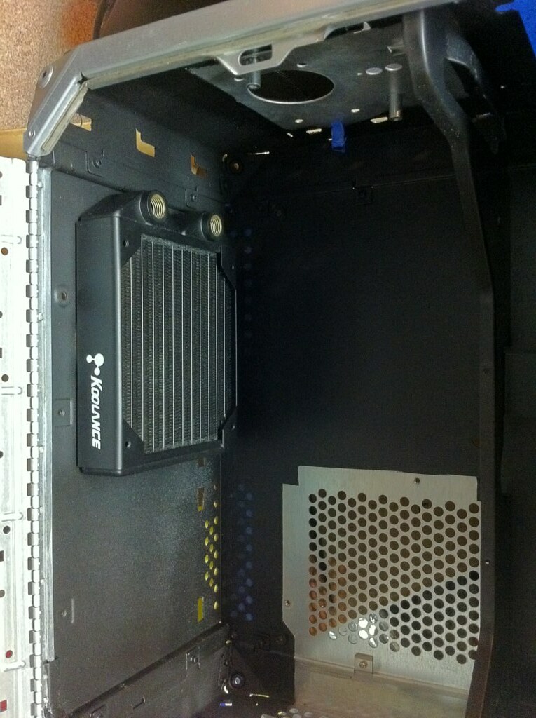
  • Avoid cutting visible fan holes in the case. Airflow is definitely an issue in this chassis with a modern CPU. My plan to combat this is to watercool the system, with the radiator exhausting out the bottom of the chassis where its hole is conveniently concealed from the outside.[/*:m:3kxx5qh6]
  • Retain all functionality of the original Power Mac G4. A lot of the mods I have seen give up the internal optical drive in order to make everything fit. **After exploring many ways to do this, I eventually abandoned this plan. It was certainly doable, but I ultimately decided that I almost never use optical media for anything and leaving the space open gave me too many other options. A USB optical drive is in my desk drawer for the rare occasion I need to burn a disc.**[/*:m:3kxx5qh6]
  • Clean look on the inside. Let's face it, a modded case is going to be opened and inspected by every enthusiast that you meet. And I'm using an Apple chassis. If it wouldn't have met Steve Jobs' approval, I don't want it in my design. This is going to make cable management extremely important.[/*:m:3kxx5qh6]
  • Upgradeability. If I do things right, upgrading will be as simple as dropping a new mATX board into a regular ATX case. This is important, because I do upgrade frequently, and I don't want to have to re-mod every time I want to do this.[/*:m:3kxx5qh6]

So that's the introduction! I've been working on this for a month or so now and documenting as I go, so I'll be posting updates as soon as I have time to write it up. As always, feedback and ideas are welcome as you guys are pretty amazing at coming up with clever solutions to stuff. :)
 
The first step, of course, was to remove the G4 innards and strip the case down to the bare chassis so I could get a better idea of what I would need to do. This revealed some things that were going to be more complicated than I thought, but also some opportunities.

7753149134_d757d655bd_b.jpg


The door latching mechanism is achieved by the plastic panel underneath the motherboard. This slides up and down as the handle is pulled and releases the latches. It's a clever design, but it will need some modifications in order to accommodate the different standoff locations. Because I am planning to replace the entire I/O port panel anyways, I just roughly cut it out so I could get a better view of how all the parts line up.

7753150000_61650a65f2_b.jpg


The pillar between the I/O section and the expansion slots is, unfortunately, three layers thick. Not only is it on the exterior plastics, but it's also part of the metal chassis and a third layer on the back panel insert as well. This will definitely have to go as it's definitely a major obstacle. So that I could get a better idea of how stuff was going to fit, I grabbed a dead junk mATX motherboard and tossed a PCI card into one of the slots to start experimenting.

7753150542_615ee19ed8_b.jpg


Conveniently, not one of the motherboard standoffs lines up with the original Apple ones, but this isn't surprising. Aside from this, the board is basically the same size as the G4's logic board and fits quite nicely.

7753151098_c2364ac235_b.jpg


One pleasant surprise is that the back panel is not actually part of the chassis structure but is simply riveted in like you'd find on most PC chassis. I'm not sure why I hadn't considered this before, since really it makes sense, but either way it gave me an idea.

7753153294_86d4e49401_b.jpg


Out came the drill, and a few minutes later...

7753154250_175b1174da_b.jpg


A quick dig through my parts stash yielded a junk mATX case and after a few more minutes of drilling rivets, I came up with the piece on the right. The original Apple one is on the left.

7753154816_dd1c7aa2ee_b.jpg


While not identical, obviously, they're a close enough match that some minor modifications will let me drop the real ATX backplane into the G4's chassis. This is about as perfect a solution as I could hope to find, as it will easily accommodate the motherboard's I/O shield and everything is already properly spaced. Moreover, once it's riveted in and the back plastics are reattached (appropriately modified, of course), it will look stock without any obvious signs of cutting or modification. Exactly what I was looking for! :thumbup:

Before it could fit, though, that pesky pillar needed to go. So out came me favorite modding tool, the Dremel. The chassis is steel, and relatively thick at that... a good sign of quality Apple engineering. Really, it's impressively dense and solid feeling compared to most PC cases. Unfortunately, it also makes cutting a pain. I used the reinforced cutting wheels on this, as the standard ones wear down pretty quickly on this type of material.

7753155138_a28c3e61ef_b.jpg


Ten minutes, a lot of sparks, and a lot of steel dust later... victory!

7753156228_8aee9fd037_b.jpg


There's also a metal tab that runs the whole length of the I/O section which needed to get removed because it overlaps with the one on the mATX backplane. I cut this off with the Dremel as well, then used the de-burring attachment and a file to smooth down and round all the edges where I'd cut.

7753158052_001a8f2261_b.jpg


To make working easier, I drilled out the rivets and separated the side panel from the hinge. This will be easy to reattach later, but it'll make working with the motherboard tray, not to mention the rest of the box, a lot more streamlined. I also decided that I want to paint the interior of the case, so removing all the separate pieces will be necessary eventually anyways. After using the Dremel to remove all the extra metal from the chassis, it was time to test-fit the backplane... and I couldn't be happier with the results!

7753161958_8589276b11_b.jpg


Next up will be tweaking the backplane to fit perfectly, mounting the standoffs for the motherboard, and prepping for painting. More to come.
 
Thanks, flatfoot!

One of the problems I ran into with my backplane solution is that there was nothing on the replacement piece to hold it in place below the bottom slot. It seemed like it would be sturdy enough, but I didn't want to take any chances. So I cut the piece off the original Apple part just below the last slot and attached it to the new backplane using J-B Weld. This ended up being a near perfect fit, and also meant that at least that section could drop in.

7753161338_4fd93fb02e_b.jpg


Once the J-B Weld had cured, I did several test fits and bent the upper tab of the backplane to roughly match the curvature of the Apple chassis. This wasn't exact, nor did it need to be, since it was going to slide into the open space between the two edges of the chassis. I then marked the new backplane and drilled it to match the rivet holes in the chassis, clamped it in place, and got out the rivet gun.

7753164440_33b0c10e86_b.jpg


It fit together quite nicely and feels just as solid as the original Apple part! I was a bit worried about this when I started working, but it ended up working out great. I slapped together a cardboard spacer to approximate the height of the standoffs and dropped in my junk board to test the fit, and I think it's going to work quite nicely. Once I got everything lined up the way I wanted it, I clamped the board into place to hold it solid and used the trusty paint-on-toothpick method to mark the locations where I would need to mount the standoffs.

7753163750_c57617a2ab_b.jpg


At this point, I had decided that I definitely wanted to paint the inside of the case matte black. There are a few reasons for this. One, I think it looks nice, but it's also functional in a couple of ways. I'd previously experimented with using Plasti-Dip on my current Antec case a couple of years ago and was really pleased with the results. For those of you who haven't seen it before, it's essentially a colored liquidized rubber that comes in a spray can. When it dries, it has the consistency of kind of a thick vinyl tape and has the wonderful side effect of dampening vibrations just like you'd expect from a layer of rubber. Since keeping it quiet is important to me, this is a great feature. Also, I discovered while working that the G4's steel chassis tends to oxidize VERY quickly once the finish is removed. With all of the cuts and pieces I'm removing, the last thing I want is to have rust-colored marks all over the inside of my case. The Plasti-Dip will do a nice job of preventing this too.

Here you can see the finished backplane from the inside of the case. It really does fit very nicely without much modification and makes the motherboard mounting much easier. The swirls on the metal motherboard tray are from sandpaper that I have been using to rough up the surface in preparation for painting.

7753165272_30e70c3393_b.jpg


Another thing you can clearly see in that picture is the abundance of extra holes in the motherboard tray. These are from the original Apple standoffs and most are not going to be needed for my purposes. Once I had drilled the holes for my new standoff locations and made note of which original ones I needed to keep for attaching plastics and other parts, I used J-B Weld to fill the extras. I simply used masking tape to cover them on the outside, globbed in the steel epoxy, and then sanded it smooth once it had dried. They came out pretty good and should be almost invisible once the paint has been applied!

7753167306_bdcd405bf6_b.jpg


Once everything was sanded and cleaned, I started masking all the openings and edges in preparation for painting. A lengthy process, but one that's worth it in the end.

7753166260_6b156ca8a0_b.jpg


I also went back to the main chassis at this point and removed all of the inside pieces. This makes it easier to paint and get an even finish on everything. It will also put a layer of Plasti-Dip between all of the parts, which will further reduce any vibrations when I rivet them back together.

7753159306_d7b293c383_b.jpg


And after more fun with the drill...

7753160366_9055faa965_b.jpg


At the bottom of the case, you can see the 120mm hole that I cut with my friend's holesaw. This is where I am planning to mount the radiator. The feet lift the case up enough that I should be able to exhaust the hot air through the bottom, which will nicely hide the opening and leave the top of the case smooth and solid (as Apple intended!). It would have been easier to mount the radiator on the big 120mm exhaust fan on the side of the case below the power supply, but unfortunately there isn't enough clearance between the fan cage and the expansion cards to be able to add anything there. So instead, I plan to use that as an intake fan and fit the radiator below. The only downside of this is that it blocks two of the hard drive mounts, but this won't be a problem as I'll be relocating the storage anyways.

7753162694_98360f96ea_b.jpg


Masking the main case for painting was even more tedious than the motherboard tray. There are a LOT of perforations in the chassis for airflow and mounting various parts that needed to be taped up. I also needed to be careful to tape around the hinge and the latching mechanisms at the top of the case so that they would still move smoothly. I'm OK with leaving these parts the original steel color as long as the edges are nice and crisp and defined, since the silver and black color scheme actually works well together. Here you can see the main chassis as I was in the process of removing the tape. The area inside the 120mm fan cage was deliberately left unpainted so as not to reduce airflow.

7753168254_195ca75b78_b.jpg


And with the middle shelf riveted back in and test-fitting the radiator at the bottom...

7753169824_6a3ddb6769_b.jpg


The radiator worked exactly how I wanted it too, so I went ahead and attached a fan grille and screwed it in. The fan will be attached on the top of it with another protective grille when it gets to that point, but I haven't put it in yet to avoid obstructing my working space until I get the other components in. The bottom of the case from the outside, with the radiator mounted:

7753170844_489b0d4e78_b.jpg


Now that everything is painted and dried, I'm into the assembly phase for a lot of the main parts. However, there is still quite a bit of modification to do with the optical drive carrier and the power supply area before those parts can be installed. Next, I'll look at some of the custom modifications as well as interesting parts I found to solve these problems. That's it for tonight!
 
gdtrfb24 said:
Not only legendary, but fun to watch!! I thought about modding a g4 case, then realized it would be to much work.

Yeah, I thought long and hard about going a different route once I got all the plastics off... but then I figured I'd come this far, why not see it through!
 
Aside from physically fitting the motherboard into the case, the biggest problems I figured I would run into are (in order of difficulty) cooling, the optical drive housing, and the power supply. Fortunately, with some patience and a lot of experimentation, all three were solvable.

As I mentioned in the earlier posts, I am watercooling this rig as it seemed like the only way to get enough cooling capacity for my components without making it sound like a vacuum cleaner in the process. My current setup has a Corsair H50 which I have been quite pleased with. It definitely doesn't compete with high-end watercooling setups, but it does much better than any air cooler I have had and is much quieter as well. Unfortunately, it's a sealed system and the hoses are simply not long enough to be able to practically mount it anywhere in the G4 case. The solution, then, was to design my own custom system. The easiest thing to do would be an external system, but I don't like setups that aren't self-contained, so that was never really a consideration.

A couple of my friends have built very nice watercooled systems using Koolance parts in the past and have always had good luck with them. Back in the day, Koolance used to sell complete cases with all the watercooling hardware built-in, but they seem to have transitioned to selling individual components and systems these days. Perfect for me, and I know from people that I trust that their hardware is good quality. So I consulted with these friends on radiator sizes, pumps, and all those fun things and set out to design the system. One thing I will say about liquid cooling is that it is NOT cheap. I think I ended up spending about $300 on my initial Koolance order, but by this point I was committed.

For those interested, the radiator I am using is the Koolance HX-CU420V. A dual fan radiator would have provided better performance, but there was simply no place to put it and, since I am only cooling the CPU, this should be more than sufficient.

7762912140_2ac6aae364.jpg


I'm powering the system with a TNK-400, which is a nicely compact tank and pump combo unit. This should provide more than enough flow and is the smallest combo setup I could find. I may have been able to fit some of the larger units, but I also want to leave as much open space for airflow in the case as possible.

7762917622_ccddd57962.jpg


And finally, I am using the CPU-370 as the waterblock for the processor. This thing is impressively heavy and solid and seems to be very well engineered, and is also appropriately low profile since there isn't a whole lot of clearance between the board and the power supply.

7762917872_96a526b276_b.jpg


I originally planned to go with 3/8" tubing, but when I started test fitting the parts, I determined that it was too thick and kinked when trying to make the tight corners across the hinge when the door was closed. So I instead went with the smaller 1/4" tubing, which should do the job quite nicely and is much easier to route through tight spaces. I'm fitting it with a spring wrap to help keep it from kinking and also just to make it look nicer.

The optical drive and its carrier need to be shortened to a little more than half their length in order to avoid hitting the RAM and preventing the case from closing. While I was considering solutions for this, I realized that a slimline (laptop) optical drive would be the perfect size, and the fact that it's rear corner is already angled only helped the fit even more. Using an old drive I had lying around for reference, I marked the chassis, measured, and then went to work with the Dremel again. I angled the cut across on the top because I wanted to preserve the mounting tabs and there wouldn't be any clearance issues that deep in the case.

7753173436_0e1b36e2e0_b.jpg


7753174274_dcdb42c5d5_b.jpg


I actually ended up taking off another 3/4" after the initial cut was made. When I was test-fitting parts, I realized that the CMOS battery on my Rampage II GENE is placed vertically and was still having clearance issues, even though the RAM now fit just fine. :banghead: 
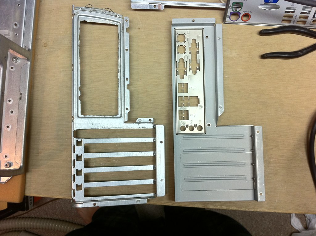
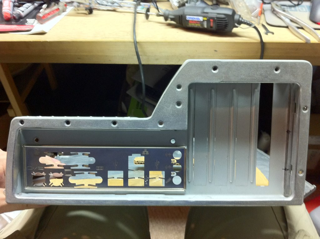
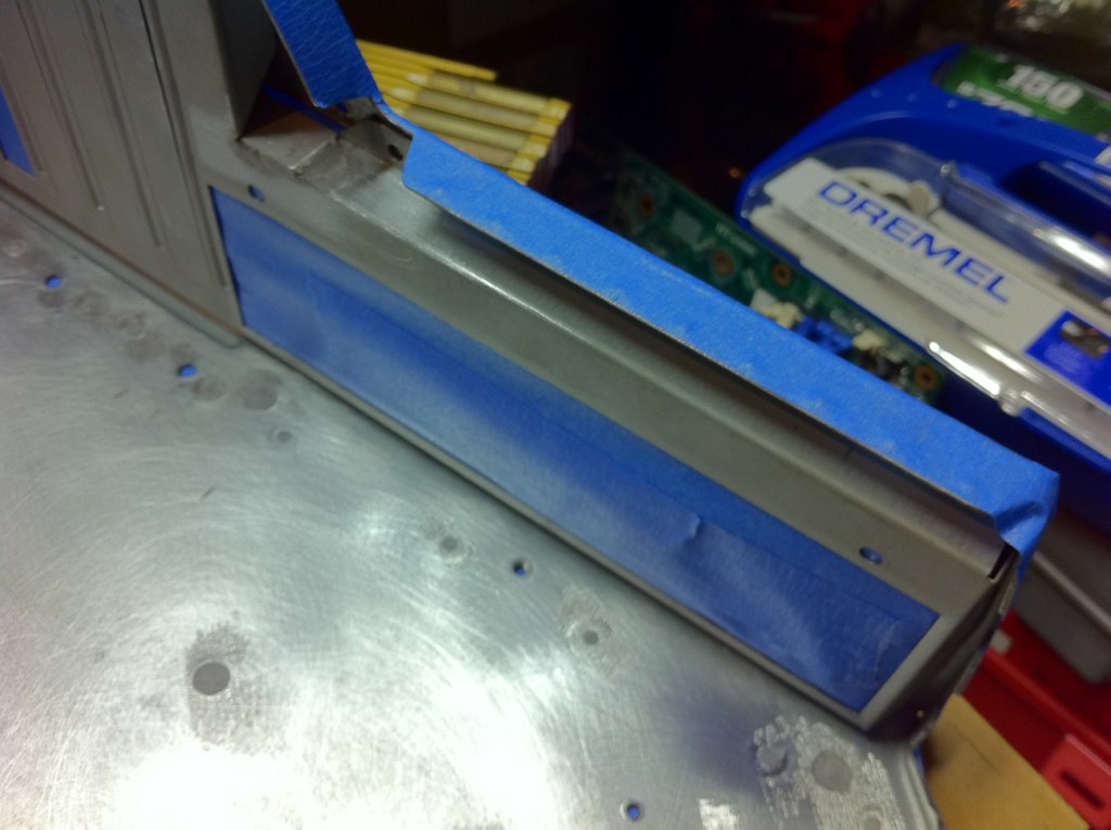
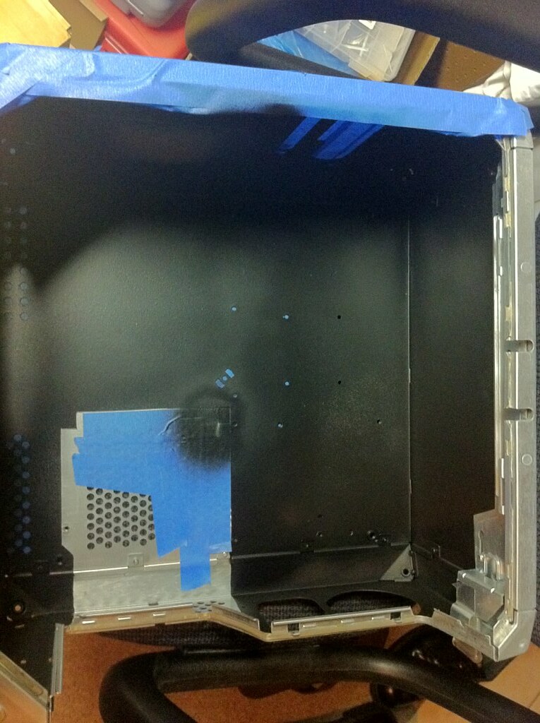
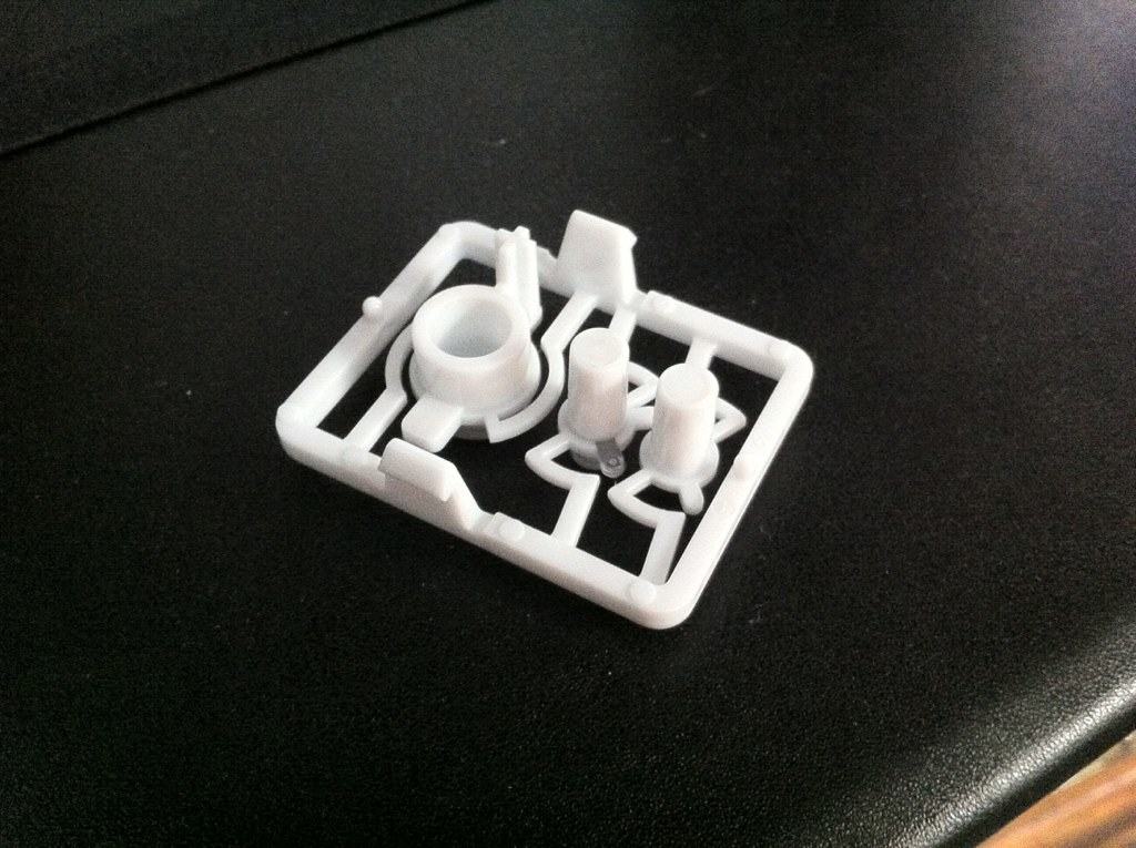
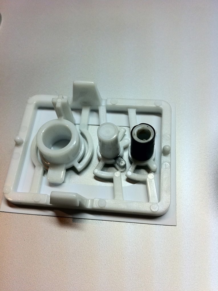
Fortunately, it was a relatively minor modification to make, and the result still looks good. The downside was that I made that little discovery after I'd already painted the part, and so had to peel off the paint (great thing about Plasti-Dip is that, once you scrape up the edge, you can peel the whole thing off like a vinyl sheet) and redo that.

Finding a suitable power supply was a bit of a challenge. The original supply is basically ATX, so the mounting points on the back all are standard as is the shape of the frame that holds it on the inside. I needed something that conformed to the basic shape of the Apple power supply and wouldn't require any huge modifications to fit. I also needed something powerful enough to run a pretty beefy system, and I wanted a modular power supply to reduce cable clutter. When I started test-fitting stuff, I also discovered that a lot of modern power supplies are quite a bit longer than the original one, which wouldn't do.

After a bit of searching and grumbling, I found that the Antec Neo HE was as close a match as I could hope to find. It had all the features that I wanted and, at 550 watts, was powerful enough for the system with some to spare. And, extra bonus, it's made by Antec, which is one of the only PSU brands that I trust! The dark gunmetal color will also work well with the black and silver of the case interior. Unfortunately, it's a discontinued model now, but I was able to find one in-stock online at a good price.

7762945794_8848643f3d_b.jpg


And installed, you can see that it's a near-perfect fit. It is slightly longer than the original power supply, but not enough to cause any clearance problems. I drilled a couple new holes on the chassis frame so the mounting bracket for the inner edge of the power supply could screw in, and I think it worked out great.

7753180614_409f6e16b4_b.jpg


One other modification I am making that will be visible from the outside is to the front panel. The Quicksilver has three buttons on the front: power, reset, and a tiny little interrupt "Programmer's Switch" at the bottom. Power and reset are obviously going to be needed as they are, but the interrupt switch is useless on modern hardware and doesn't have anything to connect to on my motherboard. It really is a tiny switch, about the size of the eject pinhole on an optical drive, and I got to thinking that it would be a perfect place to put a hard drive activity light which the real G4 lacked.

Examining the button assembly, you can see that the power button (biggest one) is hollow to allow for the power LED to shine through the outer layer. The other two, which are just switches, are solid.

7753176684_5770a05e99_b.jpg


I put the assembly on the drill press and selected a bit just narrower than the solid core of the interrupt switch, measured, and drilled down to hollow it out. Then, to prevent light leakage, I wrapped it in black tape.

7753178814_0123d3eeb9_b.jpg


After I'd cleaned it up, I popped it into the front bezel and quickly wired up a white LED to test the result:

7753179306_1ff0ca94e5_b.jpg


Of course, there will be a lot of modification needed to the front panel board on the inside to pull that off, but I think the result looks good! At this point, most of the major physical cuts and changes to the chassis itself have been made, and it's time to start installing stuff into the interior. Hopefully, I will get to that in the next couple days, but that's it for now!
 
Status
Not open for further replies.
Back
Top