Contribute
Register

Finished! G5, Twin 120mm fans at the rear and hot swap caddy

Status
Not open for further replies.
OK big guy (minihack :D) I have a shiny new G5 just itching to be worked :
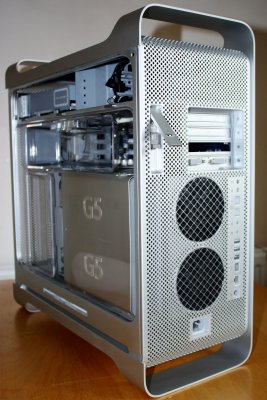
IMG_2127.jpg

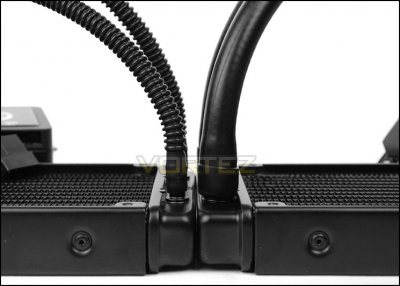
"unfortunately" I have H100i cpu cooler. I say that because it's BIG. I wished I had bought the H80i as it's half the size and would have aided easier fit into the new G5 for the sake of few degrees increase in temperature.
I also wished I had bought a microATX motherboard instead of ATX that I have.
I have what I have and love to use them in this case.

The new H100i is slightly taller than the old H100 (due to the thicker rubber tubes).
The new one is 27.8 cm tall and 12.0 cm wide.

So need advise as to best way to fit it:

1. Vertically : At the front as Intake. PSU at the bottom (where the G5 PSU used to be) ?
2. Horizontally: on the Floor as exhaust where the G5 PSU used to be. New PSU at the top where the HDD bay was.
3. Vertically: At the back as exhaust above the I/O panel - like you have the minihack twin 120 fans.

I am not sure option 3 is possible without squaring curved bottom of the case - even then not sure it's possible.

All suggestions welcomed.
 
Hi there,
Options 1 and 2 are easiest.

Option 1 can for instance be done by making a custom fan bracket/support - there is 28cm of free space between the shelf over the PSU and the DVD shelf.

Option 2 is certainly possible if you put the PSU elsewhere - e.g. use a case back that allows the ATX board to sit low in the case and put the PSU where the HDD rack is.

Option 3 may be possible. I know it can just be done with an H100, but the ATX board MUST be mounted high - as high as you can go - to get the fans to be on the flat portion AND to try and eliminate the top of the H100 from blocking the first PCI slot. I have an experimental full ATX dual 120 backplate coming in for me to play with that should just allow the H100 to fit without having to square the back off. I guess it depneds on how much taller the H100i is and if it is taller at the top or bottom - e.g. if the extra length is at the bottom a solution might be to make a rectangular slot in the floor of the G5 to allow the bottom part of the tank to just poke through. The fan depth of 2.5cm makes the reservoir bottom sit on the flat part of the floor of the G5, so a small rectangular slot may be a neat easy way to overcome the problem.

I am too busy with stuff to do any experiments right now, but I'll do my best to report back in the next couple of weeks.
 
Hey thanks minihack for considering the options.

My preference is still rad at the back - as the fan noise is further away from the ears :D

The new H100i is about 6mm longer - the extra 6mm is at the tube end:

corsair-h100i-comparetubes.jpg

That tube section is 22mm from edge to the rad body.

I agree Option 3 is very tight - I would loose the the 1st PCI slot - not ideal but on the GA-Z77X-UP5, that would be the PCI-e-1x slot - not a big deal.

I did some measurements on the empty case (as close to 1mm as I can get).
Here's what I measured (it would be good to compare against your measurements when you get a chance)
and how Option 3 might work:

View attachment H100i-placement-2.pdf

Your new experimental sounds very interesting.
 
Yes, that diagram looks about right.

One thing I am thinking of doing is instead of mounting the fans direct to the back panel, I will instead use a separate fan mounting panel from 5 or 10 mm acrylic that will also act as a fan shroud and allow me to play a little bit with the exact height and positioning of the radiator - also help to keep the new rear panel a little cleaner by not having the 8 fan mount holes.

I'll post some pic.s of the panel when it arrives and then in due course some build pic.s - not sure yet whether to go flush mount with the proto panel.

Hi minihack,
Hows the new project going ?
Any updates with pics ?

I have not started my G5 mod yet - got side tracked turning an Acer S3 notebook into an Macbook Pro. All done now so thinking about the G5 mod.
 
Hi Macnb,
The panel arrived and......I had not positioned the holes correctly to work with my new IO shield design! Doh.....
They won't be wasted though as I'm going to use them for another flush panel mod and see how that goes. So far though other things are occupying my time however. I think this one will have to wait a few weeks.
 
Hi Minihack,
Sorry to hear about the new hole positions.

I know you are busy, but if I can just pick your brains about flush mount....

I guess that means mounting the new back panel/plate flush with the existing holey case panel edge-to-edge ?
That is, fit the new back panel into the cut-out and JB-welding the complete cut-out so that it's all flush ?
Will that joint be strong enough ?
When you flush mounted your laser-cut panel to the case, how did you mount the flip-up latch to the new panel ?

Many thanks.
Mac

Strength just depends on planning how to do it right really. Nagyizom is doing the same kind of thing in the same way for a flush mount and there is no reason why it shouldn't be as strong or stronger than the original case: http://www.tonymacx86.com/powermac-g5/77146-graphite-5-a-2.html

For the flip up latch as I included the latch cut out in this build I just removed the latch mount from the original panel and JB'd it to the new one and again it was a simple robust joint.

I recently bought an edge joggler to play with to see if that might make flush mod.s quicker/neater. That is a tool for car body repairers where you make a step in an existing panel and then lap join the new panel over it. What I mean is that instead of 1. cut hole 2. JB a strip to back of hole 3. JB panel over strip you would: 1. cut hole smaller than required, 2. use the edge joggler to recess the edge of the hole and then 3. JB new panel onto the recessed panel edge. Potentially this is stronger as you are JBing onto the original case material instead of onto a stuck on strip. If you are a skilled aluminium brazer/welder you might instead be able to make the join between the old and new without JB, but I do not have those skills as yet!

Anyway, I'll let you all know on here how it goes.....
 
I recently bought an edge joggler to play with to see if that might make flush mod.s quicker/neater.

Anyway, I'll let you all know on here how it goes.....

Ah ha I too have been thinking along the same lines...just did not know what the tool was called :lol:
I sent this picture to a buddy to ask him how to do this with aluminium.
But you are already on the case :thumbup:

panel-joints.jpg

Is that what you are going to experiment with ?

PS. Thx for the other answers.
 
Status
Not open for further replies.
Back
Top