- Joined
- Dec 23, 2014
- Messages
- 41
- Motherboard
- H87-D3H
- CPU
- i7-4770
- Graphics
- HD5850
- Mac
- Classic Mac
- Mobile Phone
Hello everybody
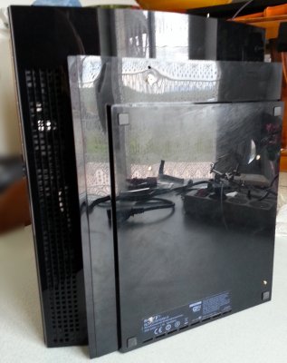
As written on the first post of this project, my aim is basically to build a small machine inside a PS3 case.
A touch button triggers ON the PS3 so I decided this mod should work with a touch sensor and create a home made circuit board.
Building the touch sensor board:
Warning, this circuit board isn’t 100% reliable and not working very well.
Maybe with some skills it can be improved, this is no longer my aim (building a 100% home made circuit).
I found some videos on YouTube with examples on how to do it.
But after spent some time and money on this I can tell this doesn’t work perfectly.
For those interested on doing home made stuff here is what I’ve done and discovered.
First, the YouTube related video on how to build a touch sensor:
[video=youtube_share;l7wXsJtnsEE]http://youtu.be/l7wXsJtnsEE[/video]
This video is very well explained except the flaws and the cons, which are:
- Any time the mains is Off and get back to On it will trigger on the circuit (computer on, led on,…).
- When you connect something on a surrounding socket it may trigger On the circuit, not so good huh?
- The wire used as touch sensor or to connect to a touch plate can’t be longer than 2 or 3 cm (one inch) otherwise the circuit will always trigger On (trigger On continuously).
- In this video the guy installed a 47K resistor (R1) and when he triggers on the circuit the Led lights On and goes off immediately after removing the finger.
This is not true with R1=47K the circuit will trigger on for 5 seconds.
Ok so these are some problems I discovered on the first attempts, building my own circuit.
Components:
Timer NE555 x1
10K resistor (1/4w enough) x1
1K resistor (1/4w enough) x1
Another resistor depending on the Led x1
LED x1
Capacitor 100MicroFarad x1
Capacitor 100NanoFarad x1
Small 5v Relay x1
Diode 1N4007 x1
Transistor 2N2222 x1
Wires
Small Breadboard
I was really surprised to find that the components are really inexpensive.
I recommend buying a solder less board to test everything before making the real circuit. I found a brand new solder less board + 65 wires for 5 euros (5$) with free shipping costs on eBay.
I’ve followed the video and the circuit worked like on the video except for the On timing delay. The led stayed On for 5 seconds after trigger On. In the table below you’ll find the ON timing depending on the R1 resistor value


Next I had a relay, which didn’t work very well:
1) When using a relay always use a diode in parallel to the relay take a look on the wiring diagram or just Google “relay diode” you’ll find many examples.
This is to avoid a problem, which can destroy the IC (integrate circuit= the timer, transistors,).
2) Wasted many hours because after trigger On the relay never get back to Off position (always on). After many hours I discovered on a forum a simple way to solve this. Instead of feed directly the relay coil from the timer, a simple transistor should feed the relay coil. After receiving the transistor, it worked like a charm, On and Off, yay !
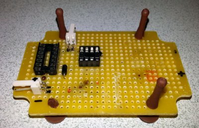
So I soldered the components to the PCB (first time ever soldering components to a PCB), and discovered the problems aforementioned. This circuit can’t be used, as is, because it’s not reliable.
[video=youtube_share;EY7bRafRi0g]http://youtu.be/EY7bRafRi0g[/video]
This is the video of my circuit board.

First time ever soldering components to the board.
After struggling during hours and days I’m not going to use this circuit.
I’ll use an out of the box solution already tested on this forum; You’ll see this solution probably on the next post.
Tips and tricks:
When using a LED you’ll have to use a resistor.
Basically this resistor must be installed between the positive terminal and the LED.
Here is the formula to find out the resistor value.
R= (V1 – V2) / A
V1 = The PSU voltage in volts
V2 = The LED voltage in volts
A = The LED amperage in Amps (not in milliAmps huh).
R= The resistor value.
Here is an example:
My PSU delivers 5V (volts) between the positive and the negative (ground) terminal.
So V1 = 5V
My green LED voltage is 3.2 V (volts) so V2= 3.2V
The led amperage is 20 mA (milliAmps) but on my formula I need Amps not milliAmps so we need to divide by 1000 to find the value in Amps 20/1000=0.02 A so A=0.02 A (Amps).
R=(5-3.2) / 0.02 = 90 Ohm
The resistor value, which will be installed between the positive terminal and the LED is 90 Ohm. Depending on the LED the voltages aren’t the same. Some times the resistor value founded doesn’t match with a real world resistor value you just need to use the closest resistor value available. Example, if you find 97ohm just use a 100ohm resistor.
Extra tip: LEDs have a polarity, meaning you can’t reverse + and – LED terminal.
It’s easy to recognise de + and the – of the led. The longest “leg” is the positive one.
Extra tip 2: To keep in place the components before soldering, you can use superglue.
Doing a monolog isn’t so cool. I know there are silent readers just like me before writing this. I’ll really appreciate your point of view, comment, questions and tips. Thank you for reading. You’re welcome.
Stay tuned for the next episode of the PS3 case mod.
As written on the first post of this project, my aim is basically to build a small machine inside a PS3 case.
A touch button triggers ON the PS3 so I decided this mod should work with a touch sensor and create a home made circuit board.
Building the touch sensor board:
Warning, this circuit board isn’t 100% reliable and not working very well.
Maybe with some skills it can be improved, this is no longer my aim (building a 100% home made circuit).
I found some videos on YouTube with examples on how to do it.
But after spent some time and money on this I can tell this doesn’t work perfectly.
For those interested on doing home made stuff here is what I’ve done and discovered.
First, the YouTube related video on how to build a touch sensor:
[video=youtube_share;l7wXsJtnsEE]http://youtu.be/l7wXsJtnsEE[/video]
This video is very well explained except the flaws and the cons, which are:
- Any time the mains is Off and get back to On it will trigger on the circuit (computer on, led on,…).
- When you connect something on a surrounding socket it may trigger On the circuit, not so good huh?
- The wire used as touch sensor or to connect to a touch plate can’t be longer than 2 or 3 cm (one inch) otherwise the circuit will always trigger On (trigger On continuously).
- In this video the guy installed a 47K resistor (R1) and when he triggers on the circuit the Led lights On and goes off immediately after removing the finger.
This is not true with R1=47K the circuit will trigger on for 5 seconds.
Ok so these are some problems I discovered on the first attempts, building my own circuit.
Components:
Timer NE555 x1
10K resistor (1/4w enough) x1
1K resistor (1/4w enough) x1
Another resistor depending on the Led x1
LED x1
Capacitor 100MicroFarad x1
Capacitor 100NanoFarad x1
Small 5v Relay x1
Diode 1N4007 x1
Transistor 2N2222 x1
Wires
Small Breadboard
I was really surprised to find that the components are really inexpensive.
I recommend buying a solder less board to test everything before making the real circuit. I found a brand new solder less board + 65 wires for 5 euros (5$) with free shipping costs on eBay.
I’ve followed the video and the circuit worked like on the video except for the On timing delay. The led stayed On for 5 seconds after trigger On. In the table below you’ll find the ON timing depending on the R1 resistor value


Next I had a relay, which didn’t work very well:
1) When using a relay always use a diode in parallel to the relay take a look on the wiring diagram or just Google “relay diode” you’ll find many examples.
This is to avoid a problem, which can destroy the IC (integrate circuit= the timer, transistors,).
2) Wasted many hours because after trigger On the relay never get back to Off position (always on). After many hours I discovered on a forum a simple way to solve this. Instead of feed directly the relay coil from the timer, a simple transistor should feed the relay coil. After receiving the transistor, it worked like a charm, On and Off, yay !
So I soldered the components to the PCB (first time ever soldering components to a PCB), and discovered the problems aforementioned. This circuit can’t be used, as is, because it’s not reliable.
[video=youtube_share;EY7bRafRi0g]http://youtu.be/EY7bRafRi0g[/video]
This is the video of my circuit board.

First time ever soldering components to the board.
After struggling during hours and days I’m not going to use this circuit.
I’ll use an out of the box solution already tested on this forum; You’ll see this solution probably on the next post.
Tips and tricks:
When using a LED you’ll have to use a resistor.
Basically this resistor must be installed between the positive terminal and the LED.
Here is the formula to find out the resistor value.
R= (V1 – V2) / A
V1 = The PSU voltage in volts
V2 = The LED voltage in volts
A = The LED amperage in Amps (not in milliAmps huh).
R= The resistor value.
Here is an example:
My PSU delivers 5V (volts) between the positive and the negative (ground) terminal.
So V1 = 5V
My green LED voltage is 3.2 V (volts) so V2= 3.2V
The led amperage is 20 mA (milliAmps) but on my formula I need Amps not milliAmps so we need to divide by 1000 to find the value in Amps 20/1000=0.02 A so A=0.02 A (Amps).
R=(5-3.2) / 0.02 = 90 Ohm
The resistor value, which will be installed between the positive terminal and the LED is 90 Ohm. Depending on the LED the voltages aren’t the same. Some times the resistor value founded doesn’t match with a real world resistor value you just need to use the closest resistor value available. Example, if you find 97ohm just use a 100ohm resistor.
Extra tip: LEDs have a polarity, meaning you can’t reverse + and – LED terminal.
It’s easy to recognise de + and the – of the led. The longest “leg” is the positive one.
Extra tip 2: To keep in place the components before soldering, you can use superglue.
Doing a monolog isn’t so cool. I know there are silent readers just like me before writing this. I’ll really appreciate your point of view, comment, questions and tips. Thank you for reading. You’re welcome.
Stay tuned for the next episode of the PS3 case mod.


 ) you’ll be able to use a PS3 BD (Bluetooth) remote flawlessly. Remote Buddy includes a KODI plugin and the PS3 BD remote will work out of the box no need to setup each button of the remote.


