Contribute
Register

G5 with a twist

Status
Not open for further replies.
I have been doing some more re-thinking on the mod and thought it might be nice to make this one more of a specialised water cooling case.

As there is now a huge hole in the roof (!) I started thinking that there is not much reason to have a 120 fan at the back - as it only diverts airflow away from the roof fans.

I also started thinking that if a conventional water cooling system was to be used in a G5 then maybe there is a better - or at least different - way to route pipes and wiring.

So my latest idea is to make a full false back behind the motherboard and route the pipework around there and also give some nice options for a rear mounted watercooling reservoir.

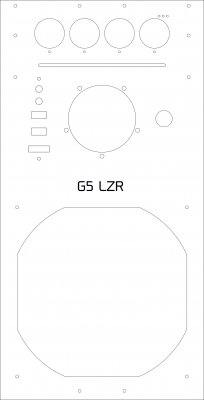
So here are the pic.s of a (another) prototype G5 back which moves everything more towards the door side to leave room underneath the IO area.

img0234xi.jpg


img0235xy.jpg

Fan replaced by a single 92mm one from the original G5 with original grill.

The large holes under the mobo area are big enough for large water pipes to be routed through or for panel connectors (maybe quick release?) to be attached for that. The small holes in line with them are 4mm holes which allow a variety of choices for mounting brackets for cylindrical reservoirs of any desired height. I've also included mount holes above and below the grill so that a shorter tube reservoir like a 150mm tube could be positioned there if wanted.

Still unsure of the exact panel design for the sides yet.
 
A bit of an update today.

After lots of measuring with bits of card and paper I have made up the first try at a full width motherboard tray for this.

The tray is cut from 5mm black acrylic (too shiney I think!) and is to be positioned for cable and (potentially) tube management.

I went full width but not full height as I need to get the PSU case in and out easily and want that to be able to be done without moving the motherboard.

So, this is me putting in the fixings to hold the tray:

p2201622.jpg


I used rivnuts (of course!) to go through the existing inner case holes.

p2201620.jpg


Unfortunately on their own they did not give me quite enough room for cable management behind the tray and then with these standoffs attached (5mm) the tray interfered with what I wanted to do with the front IO. So instead of cutting another hole in the tray (which I think would have caused a weak point) I swapped the 5mm spacers for a 2mm nut fixing. Not ideal, but it would give me about 6 or 7mm of cable management area behind the tray.

Needless to say in working out all of this my tray was removed, and re-fitted what seemed to be a dozen times.

Here is now a front view with tray and a mobo fitted for size.

trialfittingamobotray.jpg


The mobo itself is raised 22mm above the tray and gives plenty of room if I should ever decide to use the area under there for running watercooling pipes. I was initially a little surprised by how tall it was from the tray but that is just a consequence of building in those 12mm holes between IO shield bottom and where the backplate meets the case edge. There will be no big air coolers in this G5 and it has to be water all the way!!!!

After fitting the mobo in position it was time to look again at how the PSU case will work.

p2211627.jpg


I drew onto the case top the best positions for the ATX to emerge and the CPU power connection and then cut slots in the top so they can come out of the case and run into the correct positions with as little cable protruding as possible.

p2211629.jpg


Then it was on to do a bit more cable routing to work out the management.

p2211635.jpg


The SATA cables go to the right area, but I want to find some right angled cables that will stack on top of each other - anyone know where I can find some?? - then I can make a closure to cover up most of the cable hole here.

The enclosure variant I'll be using now is this one:

p2211632.jpg


I like the matt black sides and think it will fit the build interior nicely.

hotswapperadapted.jpg


Here it is trial fitted.

p2211634.jpg


When it is finally in position it'll sit on the custom PSU cover plate and be screwed in to the power supply left hand top screw. It will also be fixed to the mobo tray by some spacers to both keep it steady but also add strength to the tray itself.

There is quite a lot of room to the right of the hotswapper and in fact it could be used for two more fans - or maybe to internally mount a reservoir if I ever get the cash and hardware desire to move from the Kraken x60.

Finally, here are some more views of the front IO as it is now.

p2211630.jpg
]

I worked out the fixing to the tray and also to the internal standoffs. However, the decision to keep the front switch and LED combo is not necessarily a great one. While the intention is to allow a flush mounting option that looks a little more original than some, the soldering of the tiny switch PCB is a PITA. When doing that part of the mod I lifted the trace to the + side of the LED and then had to wire the + of the LED direct to the front side of the board. It was stupid of me, but one small slip can easily trash this little PCB.

p2211638.jpg


The pic above shows the front IO as work in progress. It will be JB'd in place from behind and then it could be given the front flush plate treatment, but for my own industrial look for this mod I will probably stick with this:

p1181426.jpg


So it is coming along.

Decisions at the moment are that in the absence of any sponsor for using their water cooling gear in my case it will keep the Kraken X60, I also will not be putting a "door" behind the mobo tray and prefer the idea of a clean side to it. Once the cabling is in place there won't be much reason to open up that side and in any event with the new panel design it will only be a few screws to undo to get to it. I will though be sticking with my "door in a door" ideas for the opening side.

There is still a ton of stuff to do for me on this. Most of the tedious work is measuring up and then digitising where every screw and nut is and must go. It should only have to be done once of course (in theory) but in practice human error and measuring tolerances always means something is not quite right when designing a new panel from scratch.

When everything then is right and fits the way I want I still need to tear it apart again just to paint it.....this will be rolling along for some time yet.
 
minihack - I was very interested in your project as it was exploring new ground for a G5 PM hack. Do you have an update? Did you finish?

I am toying with the idea of modding the outer case on my TOP project went back to re-read the detail on this project.

Good modding,
neil
 
Sorry for the lack of an update on this one.

It IS still active, but took a back seat to the Cube mod.. What I really need to do is just sort out a few more measurements for the side panels and then get them ordered.

It doesn't help that I sold the front hot swap case and now need to build myself another too.

Still I think I have some free time on the horizon........
 
Here's your front plate in action:

c29r8HA.jpg


It has been modified a little more than from when you gave me the file ;)

Jeffinslaw
 
Sorry for the lack of an update on this one.

It IS still active, but took a back seat to the Cube mod.. What I really need to do is just sort out a few more measurements for the side panels and then get them ordered.

It doesn't help that I sold the front hot swap case and now need to build myself another too.

Still I think I have some free time on the horizon........
Hi There, did you ever get round to finishing this mod ?
 
Hi There, did you ever get round to finishing this mod ?

:oops:

This one (of all my unfinished projects) is taking the biggest back seat right now. Unfortunately the pressure of running two businesses and in creating stuff for other people means that this one is sadly neglected.

The Mac Pro mod, a corresponding G5 mod [VERY similar to the mod now on here by Scatology but not full width and bolting to the case to sandwich the G5 mesh], front IO stuff for the G5/Pro and then the usual work have taken priority recently.

Of my own incomplete mods, the Water Cube (for which I have just constructed an external 250w 12v PSU and done a test run on the expanded cooling loop with GPU as well as CPU water cooler) and the iMac G3 mod are the ones that are getting attention right now, so you should be reading more on those two sooner than the G5 one.
 
So….as promised this build is not forgotten and has come to the front of my mind once again.

I decided that I do not want to rip apart my Mac Pro Mod http://www.tonymacx86.com/completed-mods/113808-minihack-mac-pro-mod.html which has the Kraken x60 in it (keeps everything in that build really cool) and so I needed to re-think my G5.

So I have decided that it needs to be a no holds barred water cooling case.

I have attached jpegs of the front and rear design treatments.

Rear is really only changed in so much as it is now full width, front though has changed radically as it now is a full width replacement panel that features a 180mm front fan inlet positioned in the case so that it can also (in time if I get crazy enough) feature a 180mm radiator, then above that will be an all new front panel with USB3, audio and eSATA on the left, and a 16mm on/off momentary switch to the right flanking an Aquatube reservoir like this:

34012-c2ce9644.jpg

And then above it, is a slot for a possible slot loading DVD and above that the Lamptron FC10 that I have. The Lamptron though will have the black front fascia removed and is attached behind the panel.

My plan for the front panel (and the rear) material is for it to be anodised aluminium in the same type of natural colour of the G5 and that it be a bolt on panel with all of the fixings being socket head bolts throughout to keep the industrial type theme.

Plan is to have the area behind the fan mounting to be re-cycled G5 mesh so that it ties the G5 theme in. I can't just keep it as the original mesh part because the 180 fan will be in the area where the original IO was - so that needs to be cut.

The two panels are on their way to me next week (not anodised yet, just brushed) for me to check out.

The top of the G5 has already been cut for the Kraken x60 so I am getting a slim (30mm) Alphacool 280mm radiator to fit there and am also cutting the top to include a fill port for the water system.

Pump (or possibly pumps!) for the water-cooling will be modified and re-cycled pumps from the G5 ( see http://www.thelaserhive.com/2014/02/03/re-furbishing-a-g5-laing-ddc-water-pump/ ).

I am quite fired up now to take this mod forward and finish it. My current thoughts for the case surround are shifting though and I may just go with re-using an old (bent) G5 outer case by drilling the original mount points out - remember that the original outer had some of the mount points ripped when it got bent - and then using the same style socket head fixings as I am using on the front to hold the outer case to the inner case by using rivet nuts on the inner case. This way, instead of the inner case being screwed to the outer, the outer case will screw to the inner….

I also have some interesting ideas for mounting drives underneath the motherboard and accessing them from a window in the case side.

Sorry this post has turned into a ramble! I hope though that soon enough you will see where this is going.
 

Attachments

  • front.jpg
    front.jpg
    279.6 KB · Views: 147
  • Rear.jpg
    Rear.jpg
    431 KB · Views: 164
Here is a pic of the original bent outer case with me having drilled through the case screw nuts.

The graffiti on the sides is me marking down the hole co-ordinates so that it will then be easier to make up any custom side panels from a CAD file. I have also marked out a rough area where I am going to dremel out part of the side case for an access panel/ window to underneath the motherboard where I am planning to mount 3 laptop sized drives.

Drilling through the screws mounts with a 2.5mm drill bit was quite easy as the mounts centre the drill bit automatically. I then removed the remainder of the nut by using an M3 screw tap to restore the thread, screwing in a 10mm M3 screw and then knocking the screw sideways with a hammer tap. This nicely removes all the residual parts of the mount.

I am probably going to now drill the holes out a little larger (about 3.5mm) and also countersink the holes from the outside.

I am toying with the idea of trying out "hard" anodising for the outer case. To do that it will need to be sanded back (or bead blasted) to remove the original anodised coat first. Hard anodising is supposed to be much more durable than the usual "decorative" anodising and should give it a darker kind of matt finish (think saucepans/frying pans!).
 

Attachments

  • IMG_1094.jpg
    IMG_1094.jpg
    560.8 KB · Views: 180
Status
Not open for further replies.
Back
Top