Contribute
Register

MACPro G5 Case Mod

Status
Not open for further replies.
Joined
Jun 28, 2011
Messages
19
Motherboard
Gigabyte H97M-D3H
CPU
i5-4690k
Graphics
GT 240
Mac
  1. 0
Classic Mac
  1. 0
Mobile Phone
  1. 0
OK. Many people already have done it each one with a different approach. I always liked the simple look and design of the Mac Pro's case such so that I decided to get my ATX mobo and parts inside one of them. I started by looking around some for online sale adds and got myself a PPC G5 Early 2003.
I wanted to keep the case's look as close as possible of the original and to have the least or almost no cuts to it.
Here is the list of the parts I got to get my approach;

1- ASUS P8P67-M microATX Mobo
2- i5-2300 CPU
3- Corsair 16GB Vengeance
4- BFG GX 260
5- Asus USB BT
6- Dlink DWA-552 PCI Wireless Card

I’m not going over the OS installation since that information can be found in the Forums.

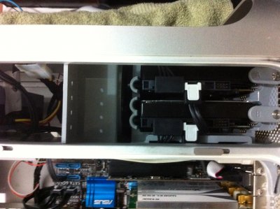
The first thing I decided to do was to mod the PSU available in the PPC case which in this model seats on the bottom of the case. My mod would be to remove the internal PPC PSU guts and add an ATX guts. Luck me that I had an Acepower PSU. After doing some mesurements it fit perfectly inside the PPC PSU enclosure.

I used the ATX PSU base and kind of screwed it to the PPC PSU enclosure. I kept the original AC plugs so I had to remove the ATX Ac plug and solder the original one in its place.

Here is the picture of the PSU mod. As the MOD progresses I will be updating this topic.
 

Attachments

  • IMG_0112.jpg
    IMG_0112.jpg
    2.4 MB · Views: 736
I've actually spent more time preparing the cables, modifying and soldering them than in the actually assembly of the case and components. Just now I realized that I forgot to take some pictures of the process, but I think it will not affect the end product.
In the pictures that follow, I removed the P3 cable from the PPC PSU and adapted it to the ATX molex. Since I wanted to keep the original HDD and DVDROM power cables I decided to make that adaptation.
 

Attachments

  • IMG_0129.JPG
    IMG_0129.JPG
    1.8 MB · Views: 492
  • IMG_0130.JPG
    IMG_0130.JPG
    1.8 MB · Views: 495
  • IMG_0135.jpg
    IMG_0135.jpg
    1.5 MB · Views: 548
This case came complete with all the hardware. When I saw that huge blue mobo, that one day was probably the fastest and most expensive computer of its day, my heart broke when I cut some the parts needed off it. I desoldered all fans connectors, cut the front panel connector and back connectors off the board. I'm not using the back connection because I think I have some shortening somewhere and I didn't have time to find it. There are really no back connections from my ATX mobo that I'm using right now. The only one that I really need, for now is the USB, which was replaced by an USB dongle cable connected to the USB connector onboard.
So let's continue.
 

Attachments

  • IMG_0126.JPG
    IMG_0126.JPG
    2.2 MB · Views: 482
  • IMG_0124.JPG
    IMG_0124.JPG
    2 MB · Views: 474
  • IMG_0122.jpg
    IMG_0122.jpg
    2 MB · Views: 551
  • IMG_0117.JPG
    IMG_0117.JPG
    1.7 MB · Views: 460
This is the final preparation to get the modded case working. I had a few issues getting the front panel wired. Always double check the numbering to avoid connecting them wrong.

Of all the original fans, I got the top HDD, front and back CPU fans connected and working @ 5V. Even though it is a bit noisy, but I think it compares to an actual PC case noise. According to my iPhone DB meter, the noise level is at 55db.

I ran new SATA data cables for the HDs and DVDRW. They were just the right size. As for the mobo, I didn't use the mobo tray that I've seen in other posts. What I did, I screwed the original poles to the mobo, applied a dab of prepared JB Weld to them and placed it in the right position inside the case. It was hold in place by the video card, so the spacing would be correct. Let it dry overnight and next day it would be hard as rock.

I connected the USB bluetooth receiver using a USB extender cable that I got from my local dollar store, cut one of the ends and soldered the female connectors that would go straight to the mobo. I did this way to save one usb port, at least for now until I receive my PCIE WLAN card and then I can connect a 4 port PCI USB card.

Thanks to all the guys here and to the other Forums that have already completed their mods and enabled me to get this one accomplished. :clap:
 

Attachments

  • IMG_0194.JPG
    IMG_0194.JPG
    2.1 MB · Views: 561
  • IMG_0189.jpg
    IMG_0189.jpg
    1.9 MB · Views: 501
  • IMG_0192.jpg
    IMG_0192.jpg
    2.2 MB · Views: 498
  • IMG_0181.jpg
    IMG_0181.jpg
    2.2 MB · Views: 510
  • IMG_0180.jpg
    IMG_0180.jpg
    1.7 MB · Views: 471
  • IMG_0179.jpg
    IMG_0179.jpg
    2 MB · Views: 486
  • IMG_0161.jpg
    IMG_0161.jpg
    1.9 MB · Views: 478
  • IMG_0160.jpg
    IMG_0160.jpg
    1.9 MB · Views: 660
  • IMG_0142.jpg
    IMG_0142.jpg
    1.6 MB · Views: 456
  • IMG_0138.jpg
    IMG_0138.jpg
    1.7 MB · Views: 468
Status
Not open for further replies.
Back
Top