Contribute
Register

BoomR's Recording Studio G5 Case Mod

Status
Not open for further replies.

BoomR

Moderator
Joined
Dec 18, 2011
Messages
1,256
Motherboard
Gigabyte Z490 VISION D
CPU
i9-10850K
Graphics
RX 580
Mac
  1. MacBook Pro
  2. Mac mini
  3. Mac Pro
Classic Mac
  1. Apple
  2. Performa
  3. Power Mac
  4. Quadra
Mobile Phone
  1. Android
I've always had a love for the design/look of the Mac desktop case form factor, starting with the PowerMac G5. Of course, as I browse the unread posts daily, I started seeing a lot of G5 case mods that REALLY got me inspired to try my hand at it. I took my collective inspiration from metaldoom, kiwisincebirth, MacTester57, and of course, depended very heavily on all the great helper posts like this one from eelhead on how to remove the upper shelf!!

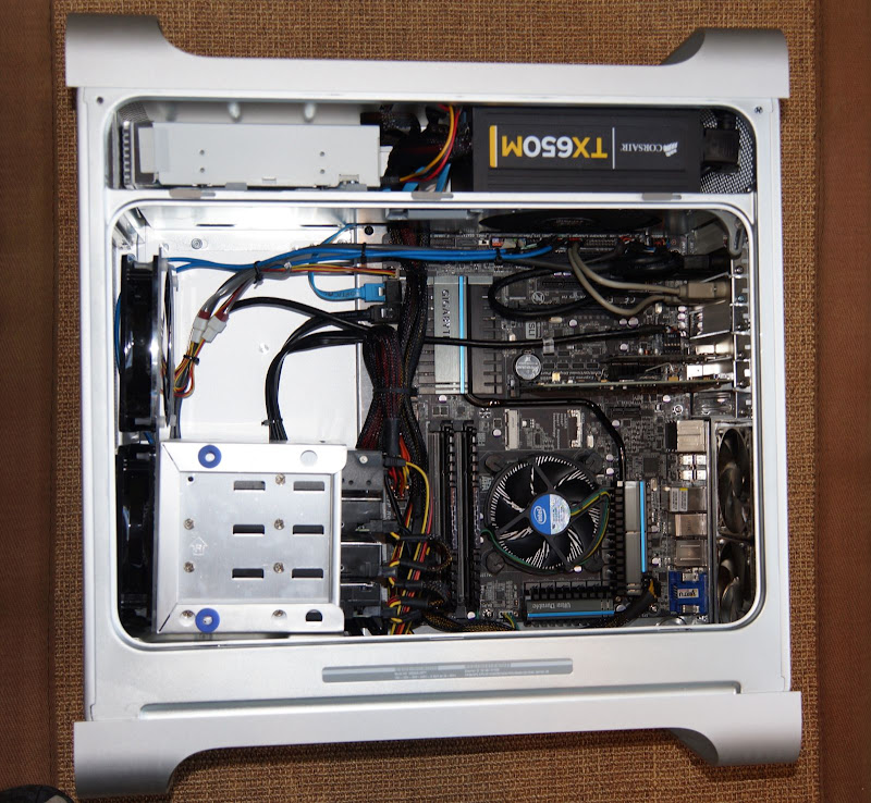
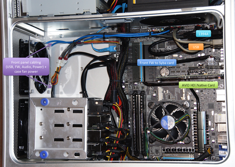
I'll make a proper post over in the user builds form that details all the components I put inside the G5 case mod, plus the various steps & settings used. But what the heck - here's a quick shot of the main build parts:
photo.JPG


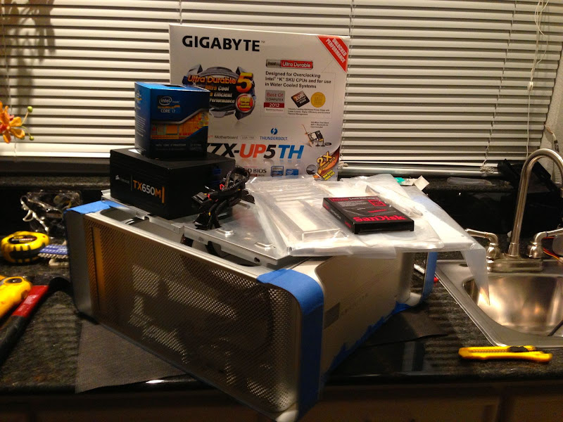
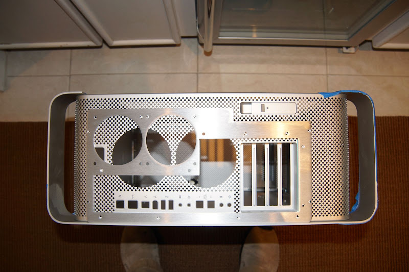
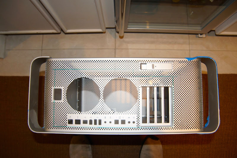
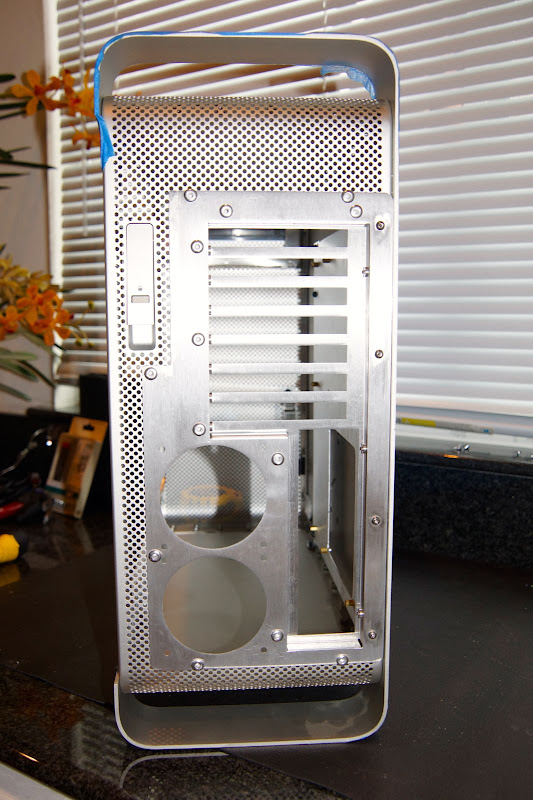
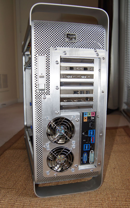
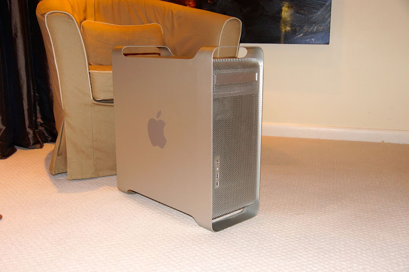
This thread is more about the actual case mod project itself. First, a few pics of the G5 that I found on Dallas Craigslist. The motherboard was fried - seller was just looking to get a few $$ to go towards a new Mini. I was VERY lucky as the case was in near mint shape:
DSC00005.JPG

DSC00006.JPG


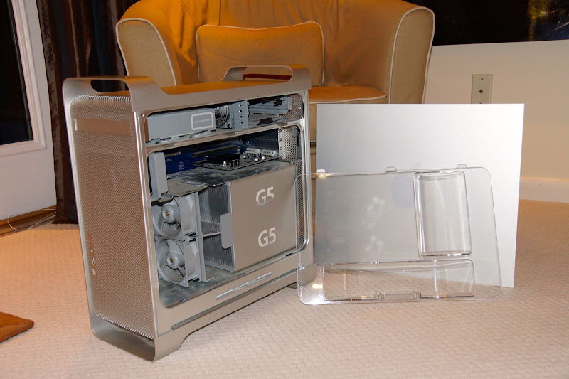
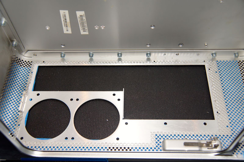
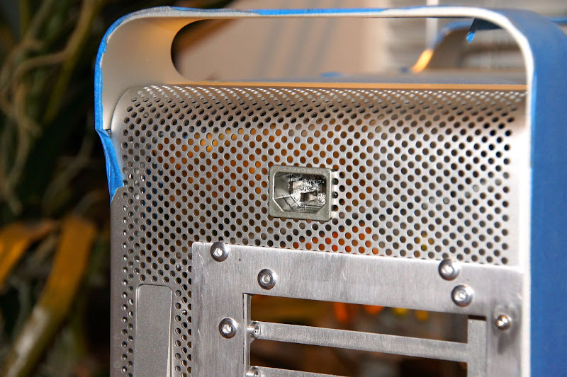
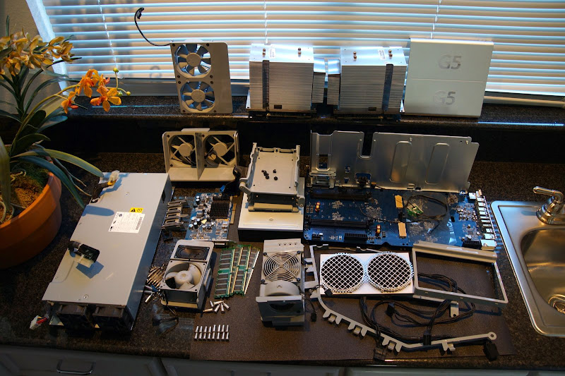
I found several "how to disassemble & gut a G5 case" on YouTube - it was pretty easy, actually, once I finally figured out the little plastic retaining clip that holds the cowl over the CPU heatsinks (with the G5 logos):
DSC00015.JPG

DSC00010.JPG

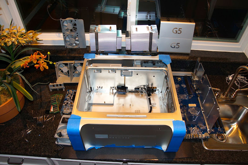
(covering all exposed surfaces of the G5 case with blue painter's tape definitely helped prevent scratches & scuffs during the case mod & assembly process).

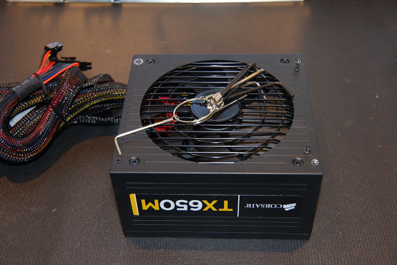
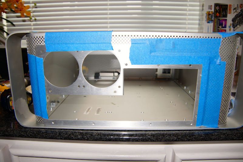
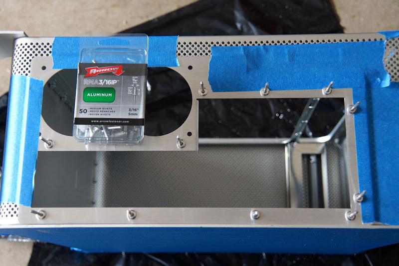
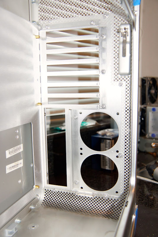
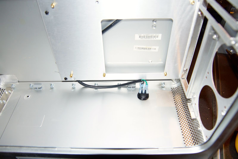
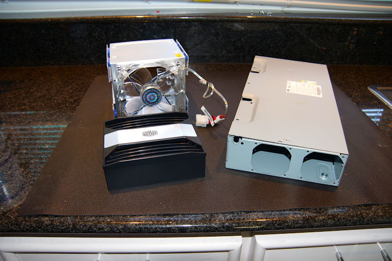
I gutted the existing power supply - not because I was going to put the new PS components inside the G5 PS case, but because I was going to use a portion of that to mount the hard drive cage that I need to hold all my HDs for this build:
DSC00017.JPG


Since this new build is replacing my recording studio golden build, I need space for 4 drives (boot drive, "work files" drive, drive for VST/sample libraries, and TimeMachine/backup drive). CoolerMaster makes a 4-by-3 hard drive cage that lets you fit 4 @ 3.5" HDs into the space of 3 5.25"/optical drive bay spaces. This was a bit more economical than one of the hot-swap multi-bay drive cages (plus I didn't need hot-swap capabilities). My intent was to cut down part of the G5's power supply case, using it's mounting screws to hold it into the bottom of the G5 case. Then affix the CoolerMaster cage onto the PS case in such a manner that it can be pivote 90 degreed clockwise so I can get to all the mounting screws in the event I DO need to swap out a drive, etc.
DSC00025.JPG
DSC00019.JPG

DSC00024.JPG

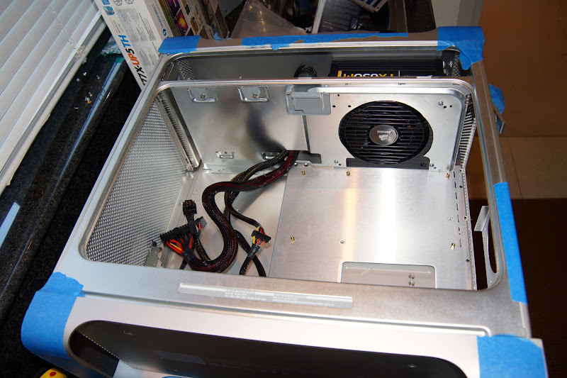
(as a side-note, I wanted to put my new Corsair modular PS up in the space where the original 2-drive HD bay was in the original G5 build, so another reason to take this approach).

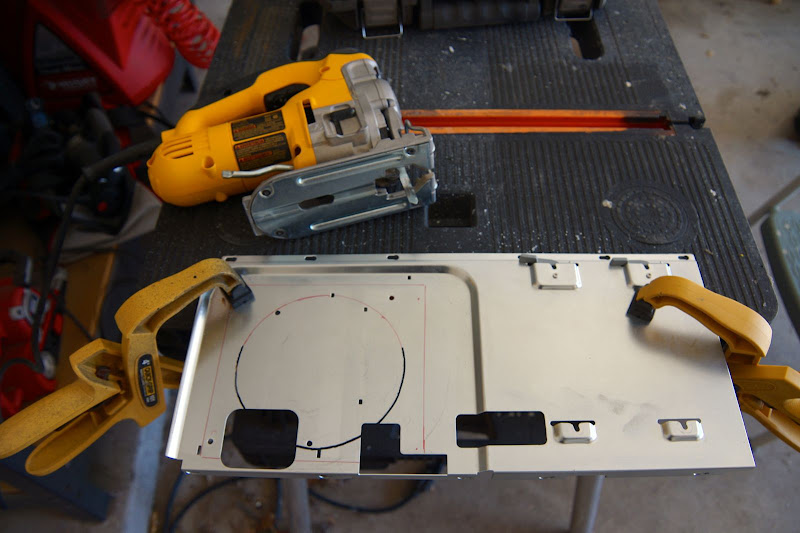
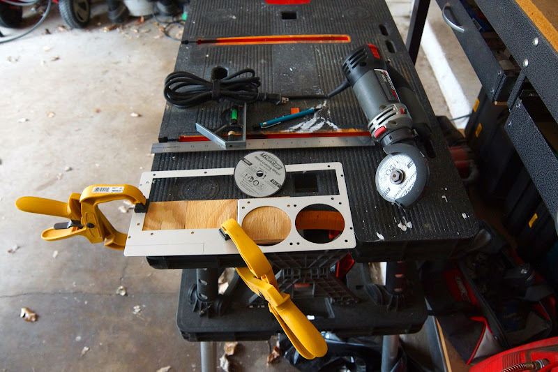
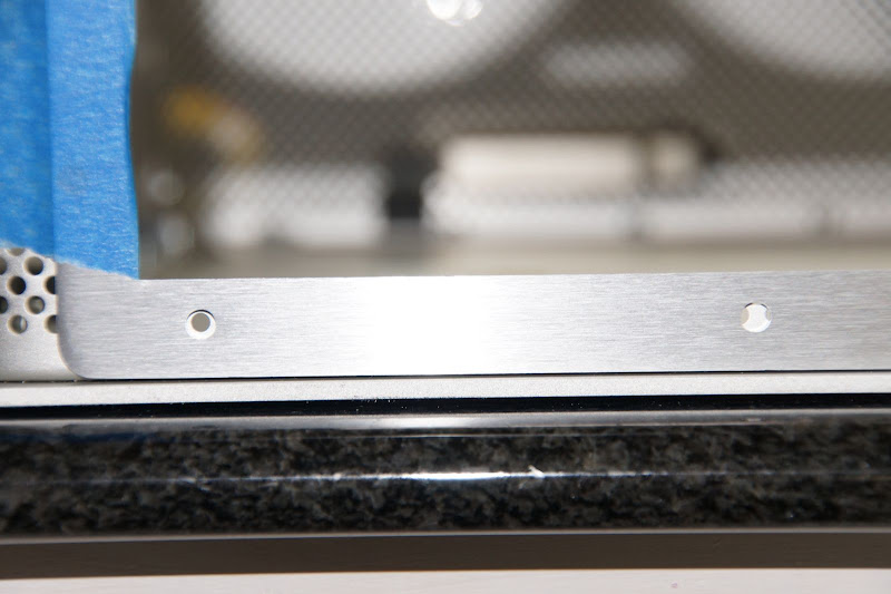
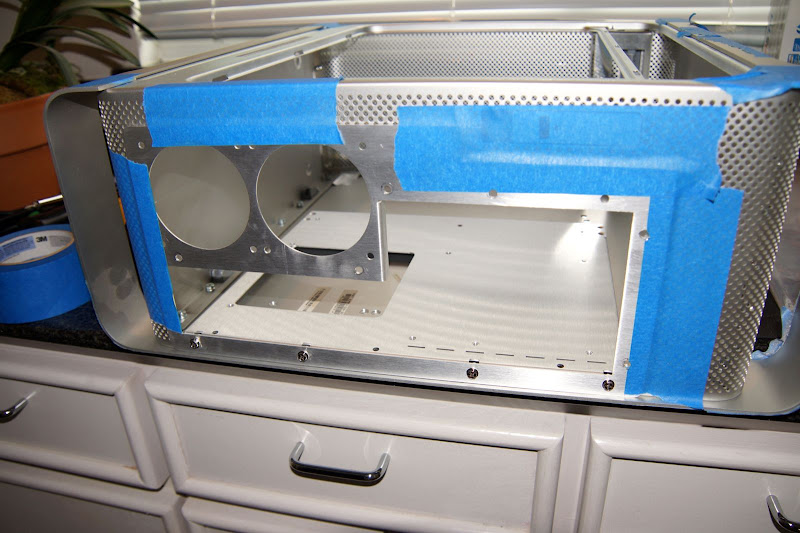
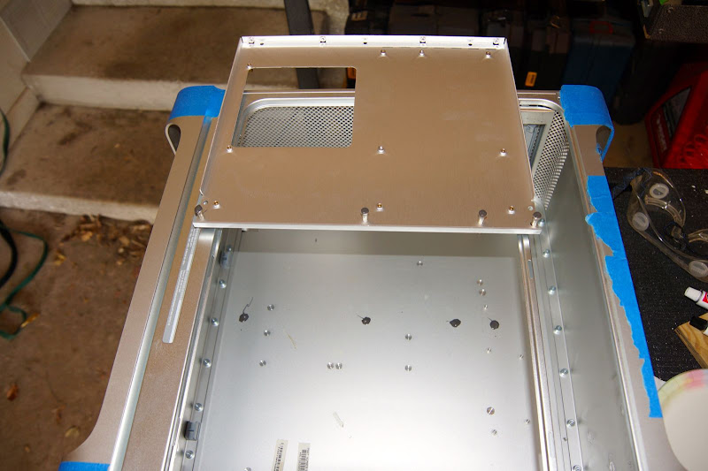
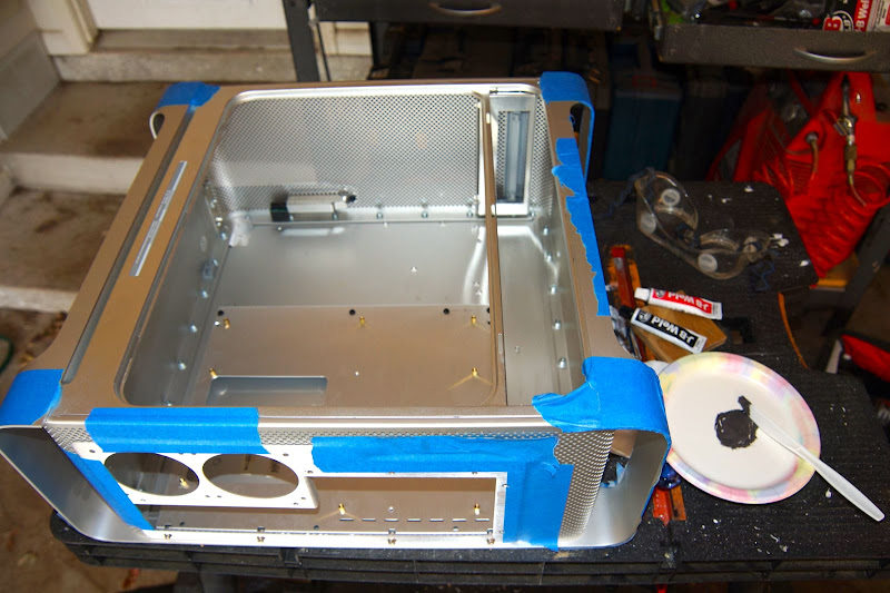
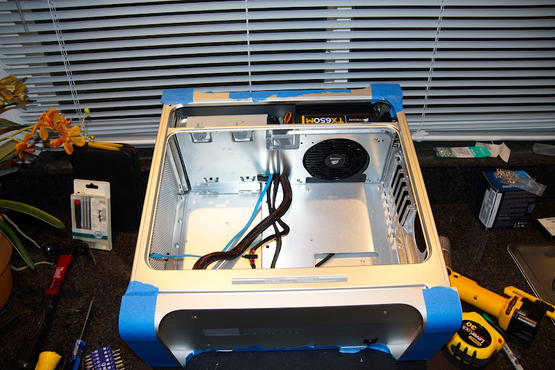
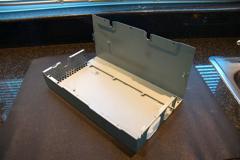
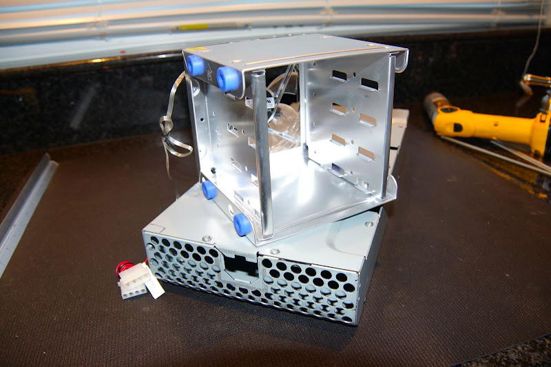
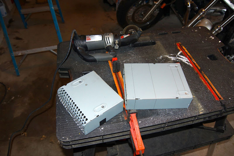
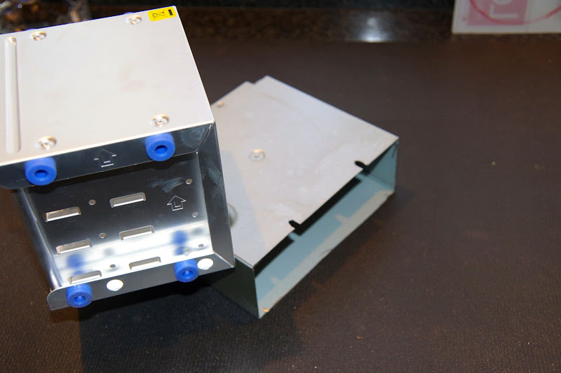
My plan is to use the Mountain Mods G5 tray with the dual 80mm fan option. I already had my motherboard in-hand, but was still waiting for the tray to arrive. So I had to "guess-timate" how much space would be needed by the tray. I trimmed the G5 PS case to leave enough room for the motherboard tray:
DSC00028.JPG


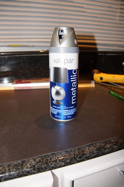
Since I would not be replacing the decorative aluminum panel that originally covered the PS, I decided to paint what's left of the PS case to better blend in with the rest of the G5 case. Lowe's had a line of metallic finish spray paints that look like they'd be a pretty good close match to the satin aluminum finish. It's the Valspar Brushed Nickel color spray paint:
DSC00029.jpg


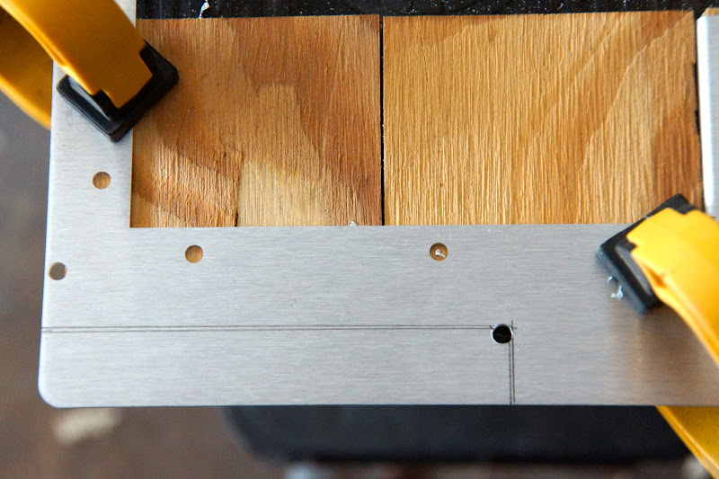
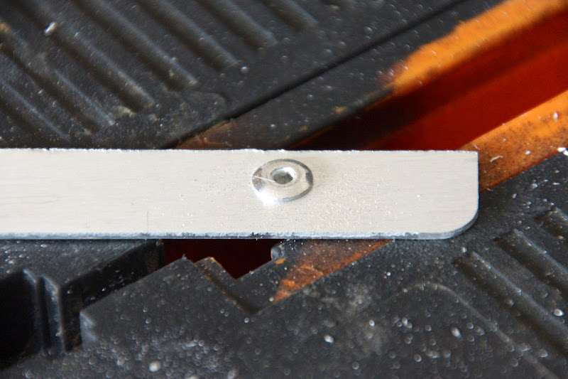
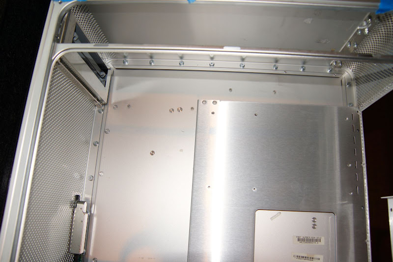
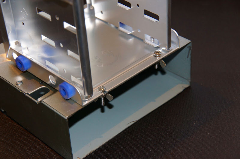
The next step was to mount the HD cage on the PS "base" - in one corner of the cage that is closest to the G5 front grill, I drilled a hole, then used my Dremel to carve out a "channel" so the cage could actually slide towards the back of the case & pivot out towards the opening:
DSC00031.JPG


I then created two additional holes & "channels" at the back to help hold the HD cage in place, but would again, let the cage slide towards the rear & let me remove the bolts (held tight using wing nuts) so it could then pivot out towards the opening. That way I could access the HD screws that would normally have been inaccessible because that side of the cage would be up against the non-opening side of the G5 case:
DSC00032.JPG

DSC00033.JPG


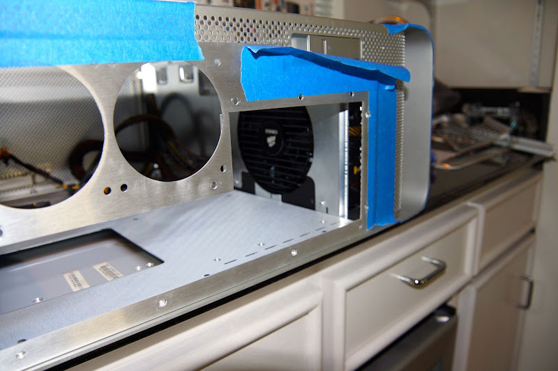
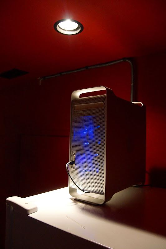
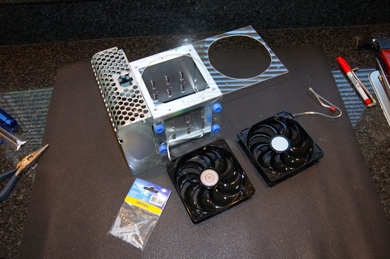
Finally, to complete this phase of the project: Fans at the front of the case. The HD cage came with a single, clear 120mm fan with blue LEDs. However, the only other CoolerMaster's 120mm case fans with blue LEDs that I could find were not clear - they were dark smoke colored. So I removed the clear fan from the HD cage, and purchased 2 of the matching CoolerMaster 120mm fans with blue LEDs so they'd have a better chance of looking the same once installed. But how to mount a 2nd fan?

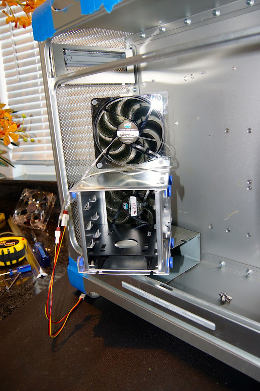
I ended up buying a piece of Lexan from Lowe's, and cut a framework that would mount to the HD cage, holding one fan in the original position at the front of the HD cage, and the other stacked on top. I thought maybe the Lexan could also catch some of the LED light and act as a lens to amplify the color across more of the front of the G5 case. Here's a few pics of that assembly (used Antech clear silicon fan mounting grommets to hold everything together):
DSC00036.JPG

DSC00039.JPG

DSC00040.JPG


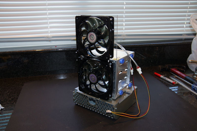
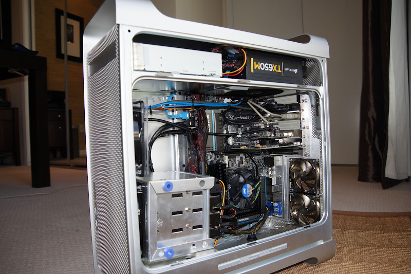
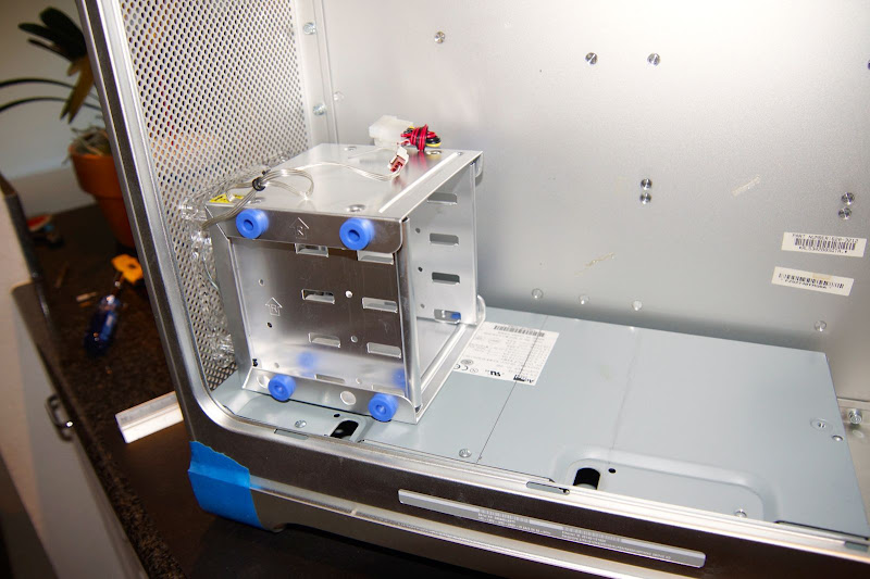
Here's what the entire assembly looks like (without the HDs) once it's mounted in the G5 case:
DSC00047.jpg


Here's what it looks like when the rear bolts have been loosened & removed, and the cage is pivoted out so as to better access the connections & mounting screws:
DSC00045.jpg


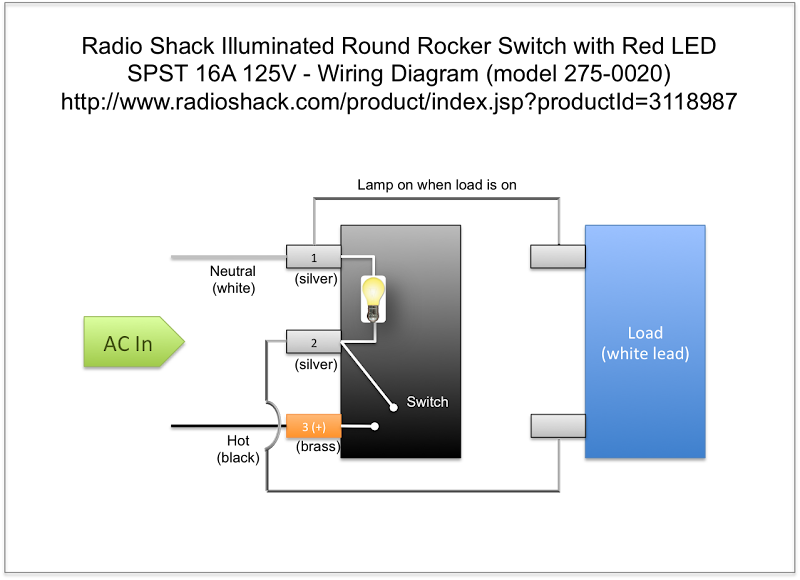
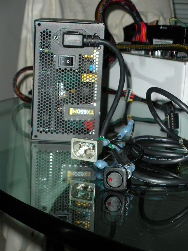
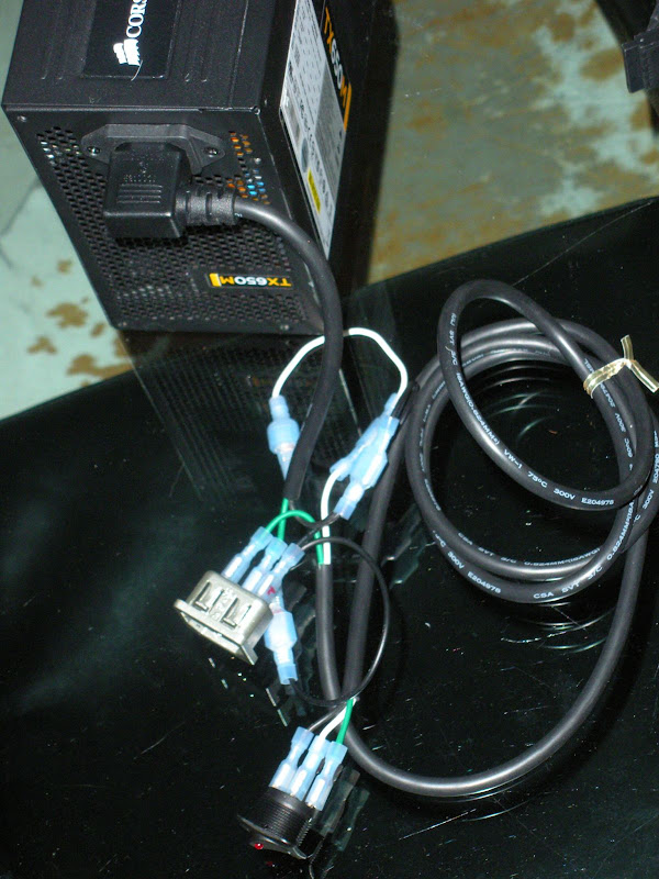
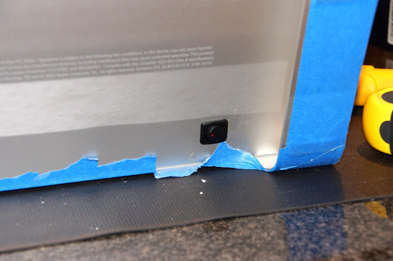
OK - end of Part 1. Part 2 coming up next, to include removing the upper shelf & doing the necessary mods to get the power supply in place (plus additional topics of dealing with the new power cord/mains connection, and wiring up an aux power switch similar to what's on the Corsair PS, but more easily accessible).

Stay tuned!!
 
I like your fan mount design. Might have to "borrow" that.

Picking up a G5 next week for $60. Guy on CL has 4 of them for sale so I can pick the best looking of the bunch. They are all working machines too and I feel bad gutting a work G5 so I will probably sell the logic board and whatever else from the inside to cover the cost of the case.


Will keep an eye on this thread.
 
Part 2: Power Supply where the 2-bay HD cage was originally located

When you remove the original HD cage, you'll notice that on the inside top of the G5 case are all the mounting standoffs for the upper HD bay. Unlike the motherboard standoffs that you can basically twist off with a pliers, these unfortunately cannot be twisted off with pliers. If you do, you risk making dents in the G5 case that are somewhat visible (depending on how hard you tried).

To remove these standoffs, I ended up using a cutting wheel on my RotoZip for the heavy lifting/cutting, followed by some coarse sanding wheels on my Dremel to get everything smooth & flush. Without removing these standoffs, my Corsair TX650M power supply wouldn't come anywhere close to fitting. As it is, I had to do a lot of extra trimming & fudging of the shelf near the final stages to get everything to fit.

Step 1 was to remove the screws that held the fan/top cover in place. It's these same screw holes that I'm going to use to secure the PS to the shelf:
DSC00049.JPG


I then created a "template" with the diameter of the fan opening, as well as the location of the screw holes. I would use this template to cut the opening for the fan in the shelf, as well as drill the holes to secure the PS to the shelf:
DSC00053.JPG


Once the template was complete, I used a fine-point Sharpie to draw the cuts and drill spots on the shelf.
DSC00055.JPG


Note that the first time around, I "guess-timated" the positioning of the power supply. Later in the build, I discovered that the positioning was too close to the back of the case, as well as too close to the non-opening side of the case. So I had to re-trim the opening & re-drill the mounting screws, as well as trim away part of the shelf that had some of the mounting screws:
DSC00078.JPG


The reason I had to trim away some of the edge of the shelf (the lower left edge in the picture above) is because again, I started doing part of this mod before my Mountain Mods motherboard had arrived. Once it arrived & I got it mounted, I realized that the tray ended up covering up some of the upper shelf mounting screws. UGH.

I don't think it's the end of the world, but now, the one end of the power supply is actually being supported by the edge of the MM motherboard tray:
DSC00080.JPG


...but at least it fits!! Now, on to the power cable port & external power switch.

I purchased the female power connector that didn't have the screw mounts. I found the link on the G5 case mod resources sticky/post. I purchased two of the snap-in IEC receptacles from All Electronics Corporation. I got two, just in case I messed up one of them :banghead:

I first got a piece of tagboard & created a template to use when cutting the mounting hole in the G5 case:
DSCN1173.JPG


The more I got to thinking about it, the more I thought how distasteful the black connector would look on the back of the G5 case. So I took some blue painter's tape and taped over all of the internal & external brass connectors, then decided to spray paint it with the same brushed nickel spray paint that I used on the G5 PS case. Here's a couple shots of the paint job:
DSCN1175.JPG

DSCN1177.JPG


Once the paint was dry, I used my template to draw the mounting hole at the back of the G5 case. Using my Dremel tool & a cutting wheel, I cut the opening for the power connector.

Before I mounted the connector on the case, it dawned on me: The power switch on the case of the TX650M would not be easily accessible. I want the ability to completely shut the power off to the motherboard when not in use (this effectively also powers down anything plugged into USB or Thunderbolt ports). So I found this SPST 16A 125v power switch with LED at Radio Shack. I had some electronics classes when I was in high school, so am pretty handy with a soldering iron & can figure out circuitry/wiring fairly easily.

I purchased a power supply cord with a right angle connector to the female socket in the TX650M. I trimmed it to about 8", and would use the wiring from this cord to wire the back end of the panel mount power connector. I then started wiring the switch into the circuit between the TX650M and the external power connector. I used the remaining 16 gauge cable from the power cord to extend the power switch down to the bottom of the case (where I would mount the switch so that it was easily reachable but not visible). Here's the wiring diagram I created to help folks who want to take the same approach:
SPST%2520Lighted%2520Rocker%2520Switch%2520Wiring.png


I used some terminal wire connectors that I found at Lowe's to make all the various connections to both the switch as well as the back end of the panel mount power connector. I didn't want to solder things here because, once I got the wiring right, I still needed to mount the power supply & panel mount jack back into the G5 case. Here's what things looked like when the wiring was complete (but not yet back in the case yet):
DSCN1181.JPG

DSCN1182.JPG


Eventually, the rocker power switch would be mounted on the bottom (at the rear) of the G5 case:
DSC00009.JPG


That's the end of part 2. Coming up next, the Mountain Mods motherboard tray installation!
 
Nice build, great work!
I think you might get problems with the HDDs / cables and the mainboard. The space between my HDD try (90° rotation) is already tight.
And be careful with the fans in the front. The closer they are to the front G5 mesh, the noiser the air "sucked in" will be.
 
Nice build, great work!
I think you might get problems with the HDDs / cables and the mainboard. The space between my HDD try (90° rotation) is already tight.
And be careful with the fans in the front. The closer they are to the front G5 mesh, the noiser the air "sucked in" will be.

Thanks for the tips - happy to report that there are no problems with HDDs/cables/mainboard spacing, nor am I having any significant noise issues with those fans. They are hardly audible - then again, my machine is in the room below my recording studio so the noise factor is not really much of a consideration.

I'll include pics of the inside of the case here shortly - you'll be able to see the positioning of everything, cable management, etc. :headbang:
 
Part 3: Mountain Mods motherboard tray & rear panel

Once again, my go-to guy eelhead has a great post on inserting the MM motherboard tray into a G5 case. Kudos, sir! Of course, since I was putting the PS on the upper shelf, the positioning of the back panel & tray was slightly "lower" than his. I think if I do another one of these, I will go the route of putting new components in the G5 PS case, and use eelhead's positioning of the tray/back panel.

The first thing to do was set a basic position for the rear plate, then measure & cut out a notch for the side panel latch:
DSC00061.JPG

I drilled a pilot hole for the corner, then used my RotoZip to do the actually work to notch out for the case latch:
DSC00063.JPG


Now that the notch is cut, I followed eelhead's instructions pretty carefully regarding placing the back panel flush with the non-opening edge of the G5 case. I then traced around the panel lightly with a pencil, then measure in "3 holes" and drew the actual line for the cutout with a green Sharpie as my guideline for the actual cut:
DSC00065.JPG

DSC00066.JPG

(looking back, I could have moved the entire panel & tray positioning a little bit further to the left in the pic above - that may have eliminated the problems I had with the tight fit of the PS and the MB tray. Lessons learned!)

The RotoZip tool with the metal cutting disk proved to be a pretty awesome way to do the cutout. Here's a couple pics of the MM back panel positioned on the G5 case once the cutout was complete. Again, using blue painters tape to hold things in place while I continue the process of positioning & mounting the MB tray:
DSC00068.JPG

DSC00070.JPG

DSC00067.JPG


As you can see by the close-up, some of the rear panel mounting holes match up with the G5 holes; some do not. So I made sure to drill out any spots where I didn't have good clearance. Another reason why I needed to make sure the holes had good clearance: I was not going to use the traditional PC case screws to secure the back panel to the MB tray I/O & PCI bracket. To me, that was a bit too "industrial" or clunky looking. I chose to use rivets which I thought was somewhat more sleek look (here's a test shot):
DSC00072.JPG

So of course, I made sure that the holes in what remained of the G5's back panel were big enough to get all the rivets through to the motherboard tray:
DSC00071.JPG


Now it's time to mount the MB tray inside the case. For now, I chose to use the screws that MM included with the kit just for positioning and so I could do my markup of where to position the standoffs to hold the tray in place:
DSC00073.JPG


I used a pencil to mark the standoff mounting holes on the one end of the tray:
DSC00074.JPG

When marking the opposite corner, that's when I first noticed that I was going to have problems with the shelf & power supply, as this side of the tray covered up some of the sockets used to hold the shelf in place:
DSC00075.JPG

...but as mentioned previously, with a little fudging of the PS positing, and a little more trimming of the tray, I was able to get it to fit (with the PS resting/being supported by the edge of the tray):
DSC00076.JPG

DSC00080.JPG


For some added security, I also chose to drill 2 extra holes into the tray - so instead of being secured to the case by only the 2 standoffs in each corner, there are an additional 2 more standoffs along this side of the motherboard tray (for a total of 4 standoffs). BTW, I'm reusing the G5's original "short" standoffs here - and using JB Weld to attach to the G5 case:
DSC00087.JPG


As you can see in the pic above, I "buttered" both the standoffs and the spots on the G5 case to make sure there was good adhesion. I positioned the tray and secured it to the back panel using the MM screws that came with the kit:
DSC00088.JPG


While that was setting up, I had one small mod to the MM back panel bracket for the PCI card & I/O ports. Since I was not going to use the sheet metal screws & was going to use rivets, I needed to drill out all the threaded grommets that you would normally use to attach the back panel to the I/O & PCI bracket (thereby securing the panel & the tray to the back of the case).

Also, i didn't want to have the motherboard tray itself permanently attached to the back panel using rivets. So I found some cool aluminum 6-32 x 1/2" torx head screws that from a distance look very much like the rivets. This way, in the unlikely event I ever do need to remove the MB tray for whatever reason, I can.

Here's a few shots of the tray completely assembled now, using the rivets for most of the work, plus the 4 alum torx screws. Note that I also drilled 2 extra holes to hold the back plate in place: one below the latch mechanism, and one to the left & midway between the 2 80mm fan openings:
DSC00089.jpg

DSC00092.jpg


Note that I also used some of the washers intended to go along with the rivets to help keep the panel in place. Here are a few more shots of the back panel, but now with the power connector in place:
DSC00001.jpg

DSC00006.JPG


..and the inside with the wiring of the switch and the "jumper" cable to connect to the TX650M:
DSC00007.JPG


...and the new hardware power switch @ the rear & bottom of the G5 case:
DSC00008.JPG

DSC00009.JPG


A shot with the shelf back in pace, with both the optical drive & TX650M in place as well:
DSC00010.JPG


That's it for part 3. Part 4, some final shots of getting all components squared away inside the case, cable management, etc. I'm off to grab a bite - more in a bit!
:headbang:
 
Great build so far! I am enjoying your thread.

chaos
 
Part 4: Front panel & final assembly!

For the "how to" on doing the front panel wiring, once again eelhead to the rescue! He had very complete & concise instructions. However, I also took inspiration from chaosdesign on using a pre-wired case panel in order to have pre-wired header connections. I've got a detailed how-to as well as an updated/color coded wiring diagram here: BoomR's twist on the G5 Front Panel Quick Guide. Browse over there to see a work log for this piece of the puzzle.

Once the front panel wiring was done, the case mod for all practical purposes is done. It's just a matter of assembling all the components into the case, tidying up the wiring, and buttoning things up! I began by purchasing a couple back panel plates:

I have a couple FW music interfaces, and it was important for me to keep them on separate FW busses. I pulled the Syba FW800/FW400 card from my original recording studio CustoMac and am using that in this new build. One nice feature is that the Syba card has a FW400 header on the card. Since I would rarely be using the front panel FW400 connection, I chose to connect the front panel to the Syba card header. That lets me put one audio interface on the Syba card's back panel connections, & the other audio interface on the motherboard's FW400 connection via the FW400 backplate.

With the motherboard now mounted inside the G5 case, I began with all my header connections (front panel USB/FW/Audio/power, back panel USB & FW). The of course all the rest of the bits & pieces: CPU, RAM, all the HDs, followed by all the PS power connections and fan power connections.

Here are a few pics of the inside of the case with all components & present & accounted for:
DSC00002.JPG

DSC00004.JPG


Here's an annotated look at some of the key bits & pieces:
G5%2520annotated2a.png


As a side-note, I ended up also getting rid of my Apogee Symphony 64 card & replacing it with an AVID Pro Tools|HD Native card. The Apogee card was giving me random reboots for no apparent reason in both my original studio build as well as this new one. I chalked it up to the fact that the Apogee card was designed as a "Mac-only" product, where the AVID Pro Tools card is cross-platform. Not a single random reboot cycle as of yet, so I suspect this was the issue. Another side-benefit of having the AVID card is that it now enables a lot more features & power in Pro Tools than just the standard non-HD version! And since my Apogee Symphony I/O audio interface has a Pro ToolsHD mode, I didn't lose any functionality or audio quality at all!

A couple more shots of the final build:
DSC00007.jpg

DSC00009.JPG

...and the clear plastic shield still fits, too!!
DSC00002.jpg


...and a couple pics of the build up & running in the room below my studio:
DSC00006.jpg

(Note the cable management system running up the wall & through the ceiling into the floor of my recording studio). Here's a shot of all the connections in place in the back:
DSC00005.jpg

(and yes, it's sitting on top of a refrigerator that keeps all my musical inspiration cold!) :headbang:

...and BoomR will now live happily ever after!

Well... that is until Gigabyte starts shipping a Socket 2011 board with Thunderbolt. Then I sense another new hexacore build in my future! :mrgreen:

Thanks everyone for following along! BTW, I'll create a companion post soon over in the User Builds section that details the hardware I'm using, as well as install process, UEFI/BIOS settings, MultiBeast settings, GeekBench scores, etc. Stay tuned!
 
BoomR, I'm impressed. :clap: :clap: And that, I want you to know is high praise as I'm an Aeronautical & Astronautical Engineer who has seen some outstanding design workmanship in some back of the hanger workshops! :thumbup:

Congratulations on a great system and a well written (clear and concise) case mod description. I have enjoyed your build descriptions especially your Golden Build. I'm looking forward to this G5 system's build description. :thumbup:
 
Status
Not open for further replies.
Back
Top