Contribute
Register

Graphite 5

Status
Not open for further replies.
Joined
Oct 23, 2012
Messages
7
Motherboard
X86
CPU
C2D E8400
Graphics
GTX650TI
Mac
  1. 0
Classic Mac
  1. 0
Mobile Phone
  1. 0
Hello Everybody!

Unfortunatly the building of my Tydirium shuttle is standing in orbit. The vacuum formin machine’s bulding has been stopped for some time, this why I can not proceed with my shuttle. I haven’t been idle for a long time, at the end of July I receeved a chance that I can not refuse.
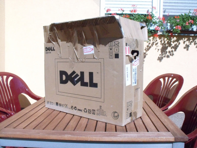
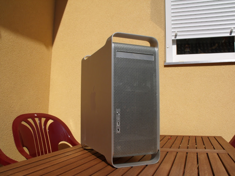
After long years of waiting I could get my hands on a PowerMacG5 chassis! I planed for a long long time to have one , but because of the price I coluld not get a chance. But in this July at a hungarian IT site’s advertise my friens saw one with a suprising low price, they called me and I negotiated with the owner in the next minute.I one week the chassis has arrived.
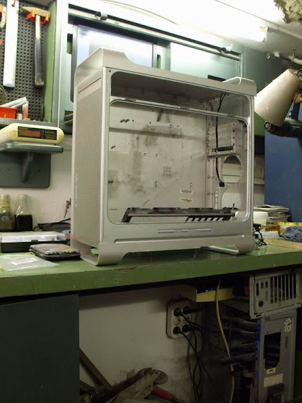
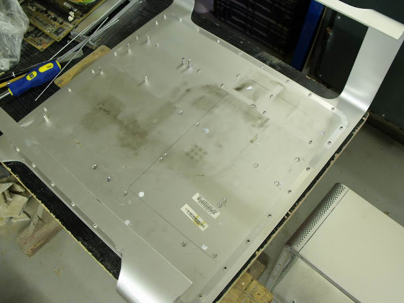
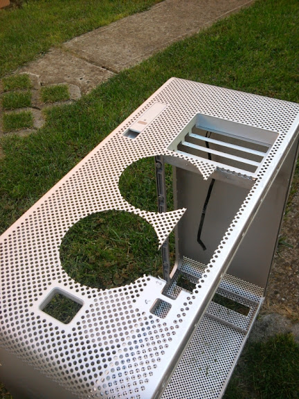
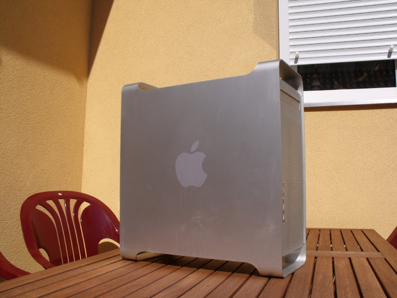
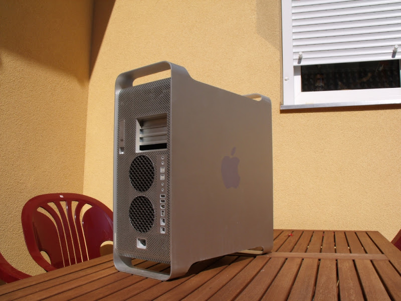
This is the chassis:

DSCF3235%2520k.jpg


DSCF3238%2520k.jpg


DSCF3239%2520k.jpg


DSCF3240%2520k.jpg


DSCF3241%2520k.jpg


DSCF3243%2520k.jpg


DSCF3246%2520k.jpg


DSCF3249%2520k.jpg

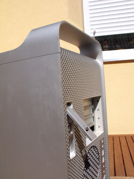
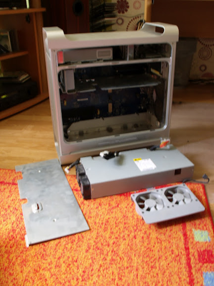
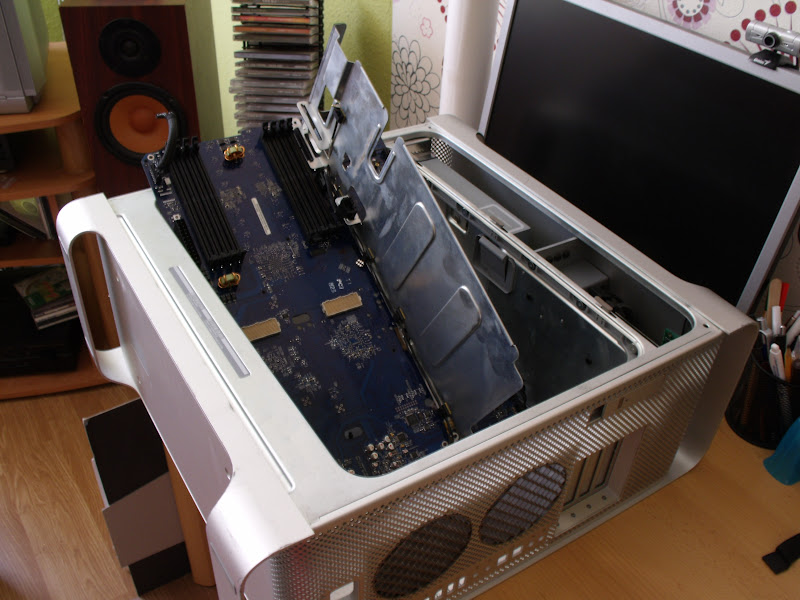
In the afternoon I removed all parts from the chassis. It was not an easy task, because I never worked with Powermac machines, I had to stop from time to time and had to think how to remove the next piece from its place..... but finally I has success and that was only important.
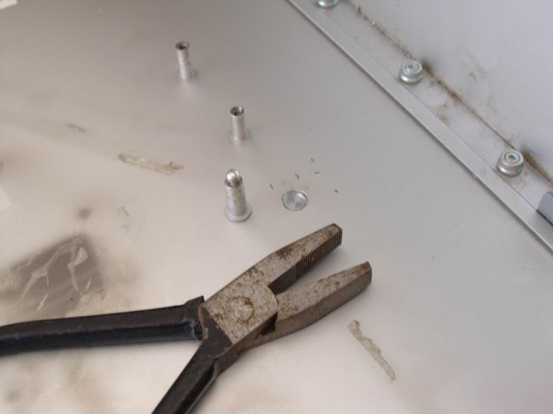
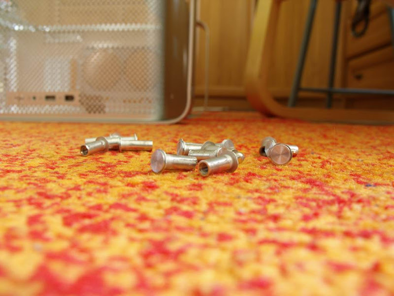
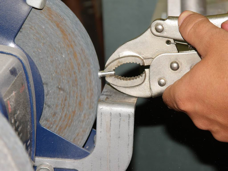
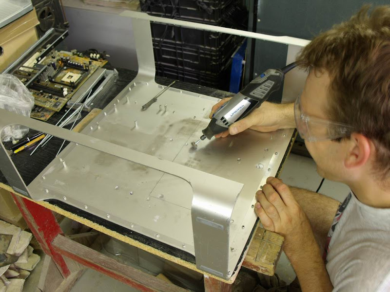
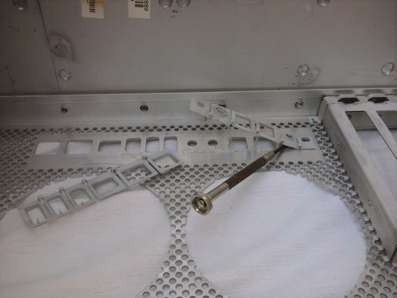
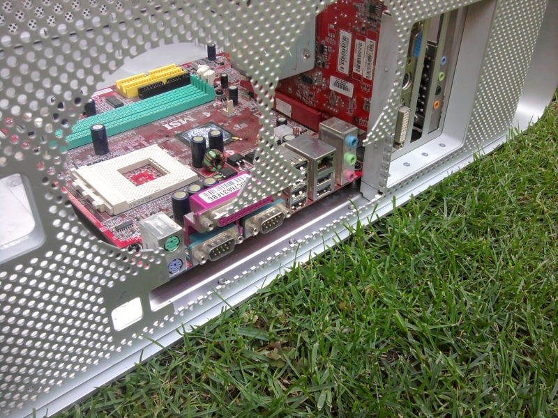
Pictures of taking apart the chassis:

DSCF3250.JPG


2012Augusztus2G5


DSCF3258.JPG


DSCF3277.JPG


DSCF3279.JPG

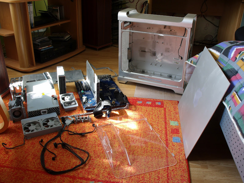
I have succesfully removed all the screws, so I can moved out all the parts left in the case. Hurray!!
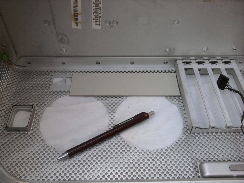
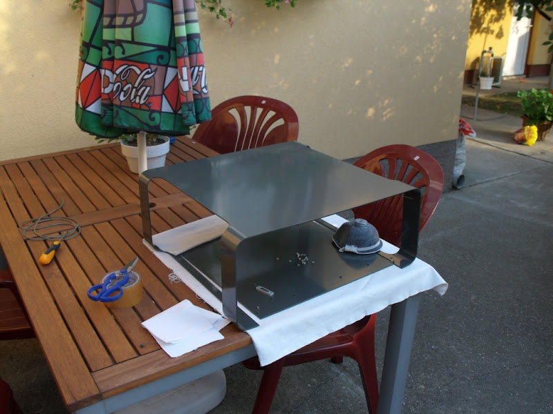
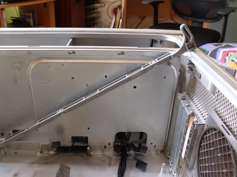
The case has been naked down totally. I can disable further to an inner core and an outer cover, but without the specific tools this is not gonna happen right now.The case has at least 3 types of screws, which need 3 different type of screwdrivers, so more is needed as a crosshead screwdriver.
My primary goal is to build a PC in this case , without modifying it too much, I am think of the backplate especially. I have to work out the fixing of the mainboard, the PSU and drives.


Thanks for reading!
 
Hello and welcome to the forum!!

I look forward to what you will turn this beauty into!
Also there are many knowledgable people here that are willing to offer advice so dont hesitate to ask any questions.

eelhead
 
Good luck with your build. Hope it turns out as fun as mine has been!
 
Thanks guys! I read a lot of useful thread on this forum, so I learned a lot of things from them.

So,in my previous quote I promised to show how will I put the mainboard in place. Previously I saw a G5 case modification here on the Bit-Tech where the owner used the original spacers to put in the PC parts. I choose this too, in my opinion this is much nicer and stylish than installing a mainboard tray.I will do it with the help of one of my friends. Previous day I removed the mainboard spacers with a pliers to solder them back like an ATX format .For this operation we had to completely dismember the case to reach the solders.
First I removed the massive ventilation grid at the back, than the screws which hold together the case.The case stands together in 4 pieces the 2 side plates and the characteristic „ears” are one, the smaller side plates the front and back panel the bottom side are the other. This can be take apart to 2 other pieces. The elements are tithed together wit screws not with rivets.

Resize%2520of%2520DSCF3313.JPG


Resize%2520of%2520DSCF3314.JPG


Resize%2520of%2520DSCF3341.JPG


Resize%2520of%2520DSCF3349.JPG

To use the spacers I had to polish the surplus stuff off. My friend has a well equipped workshop in his house at the basement, there is a grinder wich has came very handy at this time.With this grinder I removed the surplus aluminium in no time.

Resize%2520of%2520DSCF3357.JPG


Resize%2520of%2520DSCF3359.JPG


I planned to flame weld the spacers to the backplate, for this we had to know the exact size and place of them.We searched out from the stock a not working atx mainboard and to expansion cards , mounted the spacers to the board, than greased the spacers with thermal conductive paste, put the board in the right place. The paste sticked to the backplate so we can draw around the soldering. My friend roughed up the surface with a Dremel, and after the cleaning he started the warm up of the surface.

Resize%2520of%2520DSCF3372.JPG


Resize%2520of%2520DSCF3377.JPG


Resize%2520of%2520DSCF3382.JPG

After a few minutes we realized this will not work because the aluminium dispersed the heat on all over the surface, and did not warmed up the the necessary heat,and at the warming point it is became a little bit wavy. We stopped it immediately and tried to straighten the surface with weight. After the cool down , we tried to put the case together to see if the damage is acceptable. Fortunately with the screws we could pull it together.

So the soldering will not work. The solution will be the 2 component glue.

--------------------------------------------------------------------------------------------------​

The next step to make the backplate (I/O panel , fan mounting). For this I have to cut the case, I hope this part (for me the most critical) will work out fine .
It was not an easy task to measure the exact place, but with the ATX standard and another case I worked out this problem too.
My first task was the remove the original plastic edge protectors.Later I will use them up.
After This I have measured the rectangles edge place. This was the reference later I measured to it everything.

2012-08-17%252015.35.11%2520k.jpg

To draw the exact sizes , I cut out the vent from cardboard, and draw it around with a rotring.

2012-08-17%252015.35.55%2520k.jpg

I sticked to the well known saying. Measure twice to cut only one. I measured at least 3 times before started to use the machine .Before the work to have enough space I taken apart the case to 2 pieces.

2012-08-17%252016.16.19%2520k.jpg


2012-08-17%252017.25.29%2520k.jpg


2012-08-17%252018.05.36%2520k.jpg


2012-08-17%252018.06.47%2520k.jpg

Looks like the vent is on the right place. The mainboard is not completely at his place but I hope I did not ****ed up anything! :rock:

Things to do:
- Stick the spacers into the case
- Create a backplate in it's original form or at least to build it back to look like the original.
- Cut a 12cm fan hole instead of the original two 8 cm.
- I have to make the outlet look good. Have to fill the vent at the black plate and between the outlet, I think a 20x20 mm L profile will do the work.
 
Great work so far! I love all the photos and the detail you put in your write ups. Sorry to hear about your wavy case. Im glad you were able to straighten it.

Keep up the fantastic work!

chaos
 
If the spacers are also made out of aluminum you may be able to use a TIG welder to weld the spacers in place also. It's been over 20 years since I worked with a TIG welder though, I haven't done that kind of work since I got out of high school.
 
Yeah, I tried some experiments with brazing to a case a while ago. It may be my incompetence, but I got pretty lousy results....am sure it can be done but I think I would end up wrecking more cases than I would like.
 
If you notice with the G5 case and Mac Pro case all of the aluminum studs and standoffs are cold pressed in, it is done that way as to not harm the molecular structure of the metal. When heat is applied, whether it is brazing or any type of welding it changes the metal enough where as any protective coating or what not does not adhere to the metal very well, at time leaving a poor quality look. That is why when doing any welding with bodywork the weld has to be taken down quite a bit and filled at times.

With the case you might be able to braze the Standoffs on but because of the extreme heat needed you will damage the outside of the case in some way, whether it be the anodized coating or even the metal itself and aluminum is some funny metal at times to work with.
 
Looks like a great start! I am going to be following your thread closely, as I just obtained a dead quad G5 from a friend, and plan on modding it into a hackintosh case. I think the road you are going down seems like the best plan of attack. The cost of buying motherboard trays doesn't seem worth it...

Thanks for the great photos and tutorials, and keep them coming!
 
Thank You Guys! I'm glad to read your positive feedback!

Here I am with a minor update from the powercoating

I' we tried to find the best and the cheapest way to paint the case. The powercoating is makes really strong surface, easy to make it and quite cheap process. So I search for someone, who have the proper equipment for this in my town. I surprised that how close it that shop: this is in the next street of mine.

On 31.08.2012 I bring the case in this shop and started to work. Firstly, we prepared the surface with sandpaper. It was fun to remove the apple logo :lol:

DSCF4191%2520k.jpg

After this my friend Chris screwed in the screws wich I have brought and did the suspension from copper wire. Than the two parts was hanged up to the frame.

DSCF4194%2520k.jpg


DSCF4196%2520k.jpg

Before painting he washed up the full surface with white spirit to remove all staining and dust, and started the paint job. While he was painting I was filming the whole thing.

20120831
A video from the painting process:

[video=youtube;WGYXV-1dH30]http://www.youtube.com/watch?v=WGYXV-1dH30&feature=plcp[/video]​

When he finished , the next step was the burning in the furnace. It takes about 30 minutes on 200°C

DSCF4206%2520k.jpg

Then, after the burning the surface looks lik this:

DSCF4209%2520k.jpg


DSCF4213%2520k.jpg


Maybe you can ask a question: where is the another part of the case? Well, I have work with that, so I paint it after all.
The standoffs were glued into position with two component epoxy glue.

Thank for Reading!
 
Status
Not open for further replies.
Back
Top