Contribute
Register

ayilm1's G5 Case Mod (Revisited)

Status
Not open for further replies.
Joined
Jul 18, 2011
Messages
297
Motherboard
Z77X-UP5 TH
CPU
3570K
Graphics
R9 270X
Mac
  1. MacBook Pro
Classic Mac
  1. 512K
  2. LC
  3. PowerBook
  4. SE
Mobile Phone
  1. Android
COMPLETE ayilm1's G5 Case Mod (Revisited)

Current specifications

[th colspan=2] Hardware [th colspan=2] Software
CPU Intel Core i5 2500k @ 4.5GHz
Motherboard Gigabyte GA-Z68MA-D2H-B3
Graphics Gigabyte AMD Radeon HD 6870 OC Edition
Memory 12GB DDR3 1600MHz
Storage
  • 500GB Seagate Barracuda 7200RPM (OS).
  • 2.5TB Western Digital Caviar Green (Storage)
Operating System(s)
  • Mac OS X v10.7.4.
  • Windows 7 Ultimate x64


6 months ago I spent a few days throwing together a mod for an existing hackintosh. It was a rushed job and although the exterior looked fine, I grew to hate the inside. You can check it out here and spray at me about how I could do such a horrible thing to such a wonderful case. http://www.tonymacx86.com/customization/43123-yet-another-g5-mod.html

_DSC0028.JPG


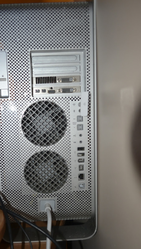
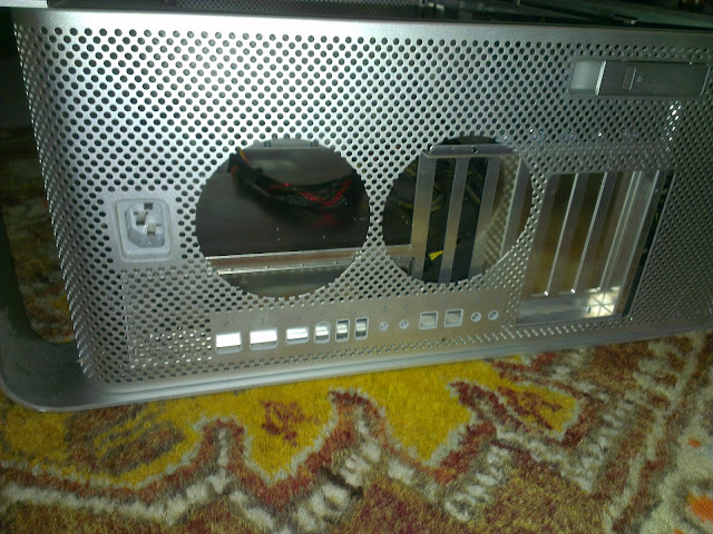
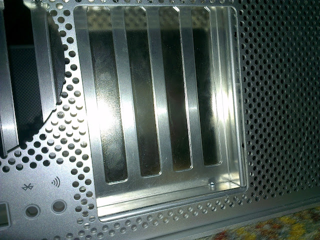
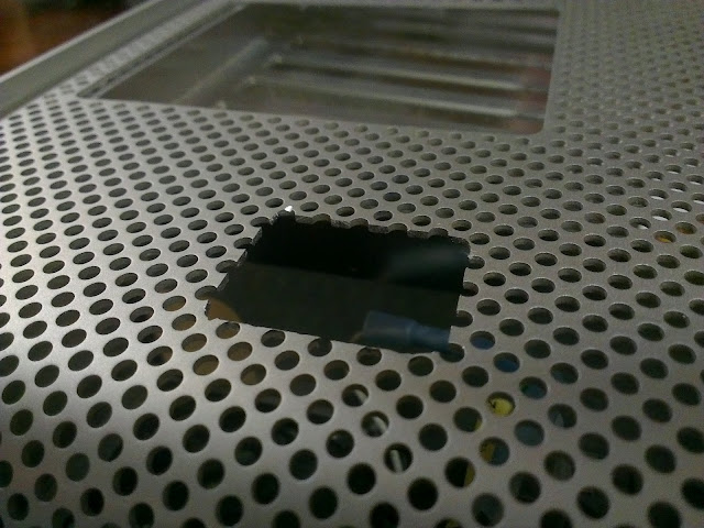
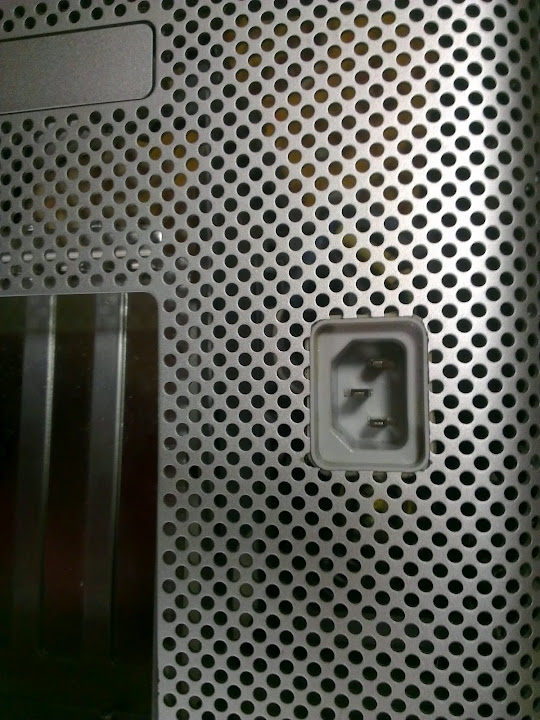
The back was left as stock as possible, but this was of course at the expense of not only limited I/O, but interior cable gore.

_DSC0027.JPG


I **** you not (excuse the language) it's much worse in person. So I've decided to revise my approach and hopefully add a few more features along the way.
 
It worked out pretty well for the some other mods, so I went ahead and treated myself to a Lian Li tray. I decided on a full ATX approach so it needed some trimming.

Went from this:

IMAG0302.jpg


To this:

IMAG0304.jpg

IMAG0303.jpg


It's actually a little better aligned now. I worked on it a bit more after this photo was taken.

The power supply was going on the top this time. A little more Mac Pro like. This will not only give me more room for a full ATX, but it'll move the drive bays elsewhere, hopefully allowing for more storage bays as well. Dremeling out the hole took a little more effort and tuning, but it turned out alright.

IMAG0306.jpg

IMAG0307.jpg


My old approach for the front panel connections was horrid. Not kidding, (check out the link) I basically jammed a bunch of wires into each of the sockets and wired it up that way. Hanging my head in shame, I bit the bullet and decided to make a quick PCB adapter for it. I still had the socket on the old G5 motherboard so I used that.

IMAG0282.jpg


I drew up a quick and dirty schematic on photoshop (My internet was cut so I couldn't get Eagle) and printed it out

IMAG0285.jpg


It transferred quite nicely despite it being plain paper. I still had to patch up some connections.

IMAG0287.jpg


I had HCL but no H2O2 so I did the unthinkable and said "I'll use saline solution electrolysis instead."

IMAG0289.jpg


It turned out OK, (Borderline crap) but since it transfers the copper through conduction, once a region had the copper surrounding it gone, I had to move the wire to complete different areas. Obviously this turned out patchy and I had to sand out some of the remaining copper. That, and I killed quite a few alligator clips in the process. So I ditched it.

IMAG0291.jpg


Round two, I went out and bought some hydrogen peroxide and it turned out much better.

IMAG0296.jpg


Tinned and cleaned

IMAG0299.jpg


Soldered on the connector and voilà, a working adapter.

IMAG0300.jpg


Preliminary cuts.
IMAG0308.jpg
 
A decidedly better approach. I think this will be a much more complete build with a better look.
 
Just a quick tip for those that don't have access to the krylon SCS-032. The Tamiya TS-83 is a very good substitute. One, maybe two shades difference between the anodised surface colour. It's slightly more reflective but only very slightly.

IMAG0313.jpg


The middle there got a bit too much, but everything centre to the far right has been painted.
 
Patch roughly cut from a slightly more destroyed case.

IMAG0315.jpg


Edges fine tuned and fan hole cut.

IMAG0316.jpg


Final placement. Not attached yet.

IMAG0317.jpg


Kind of pissed off that the hole cutter slipped. There's a scratch surrounding a quarter of the fan hole. It'll need a coat of paint after all the gaps have been filled so I might do the same for this.

IMAG0318.jpg
 
Tossed these on to make the gluing process easier.

IMAG0319.jpg


Filled in the scratch with Selley's Knead-It

IMAG0320.jpg


Prepping for painting.

IMAG0322.jpg


Finalised back

IMAG0325.jpg
 
ayilm1 I like what you are doing on this re-do. I would like to understand your PSU plan as I see you have relocated the AC entry to the upper rear.

neil
 
neilhart said:
ayilm1 I like what you are doing on this re-do. I would like to understand your PSU plan as I see you have relocated the AC entry to the upper rear.

neil

PSU is going on the top right and the drive bays are going on the left under the DVD drive. I'm planning to run the cables under the motherboard tray. Cheers!
 
Not gonna lie man this is turning out pretty awesome. I have to PowerMac cases I have modded over the years one a Blue and White G3 case and a G5 case as well. My G5 case didn't come out anywhere near as nice as this. The B&W G3 did but its painted black and red. I will have to explore doing something cool like this with my future build as I have probably 5 or 6 G5 cases just laying around doing nobody any good.

Mark
 
Status
Not open for further replies.
Back
Top