Contribute
Register

Vendetta's G5 Build (In Progress)

Status
Not open for further replies.
I see what you mean now V, Its pretty much sitting they way mine was, with the heat spreaders siting parallel with the fans for maximum cooling.
If you can bring your PSU forward toward the stock fans should give you that much more room to play with.
 
Well a quick update here. After sleeping on it and then revisiting the PSU, I feel better. Sudds has been helping me think through the PSU setup, and I'm becoming more confident that I can get it all working and keep it cool at the same time.

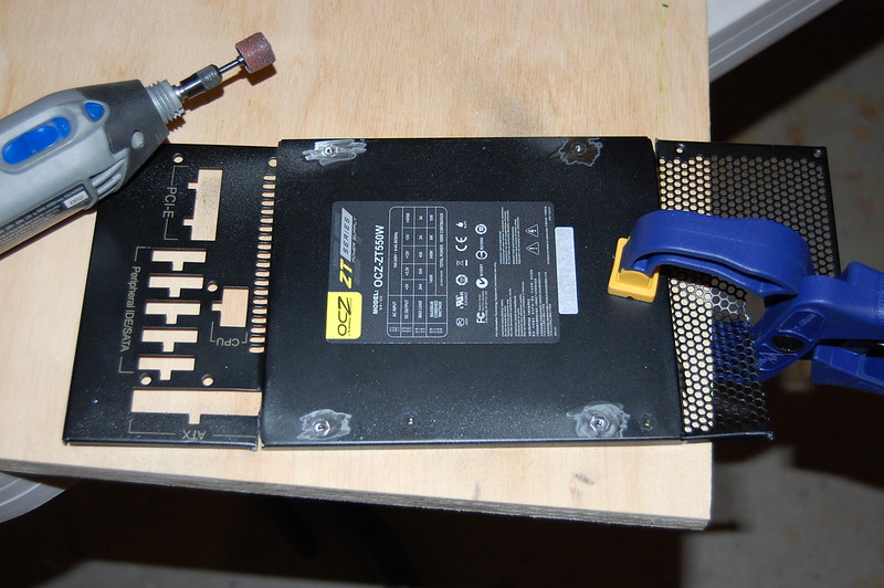
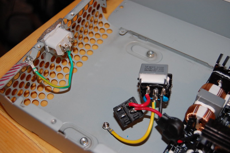
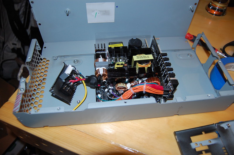
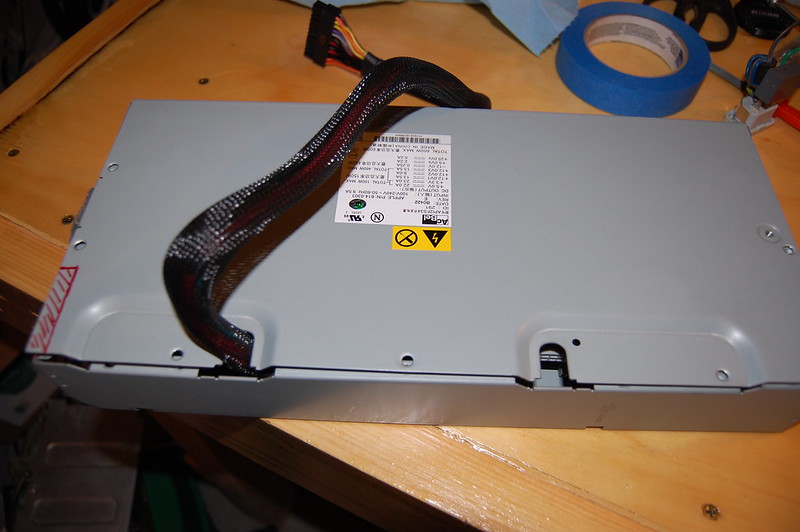
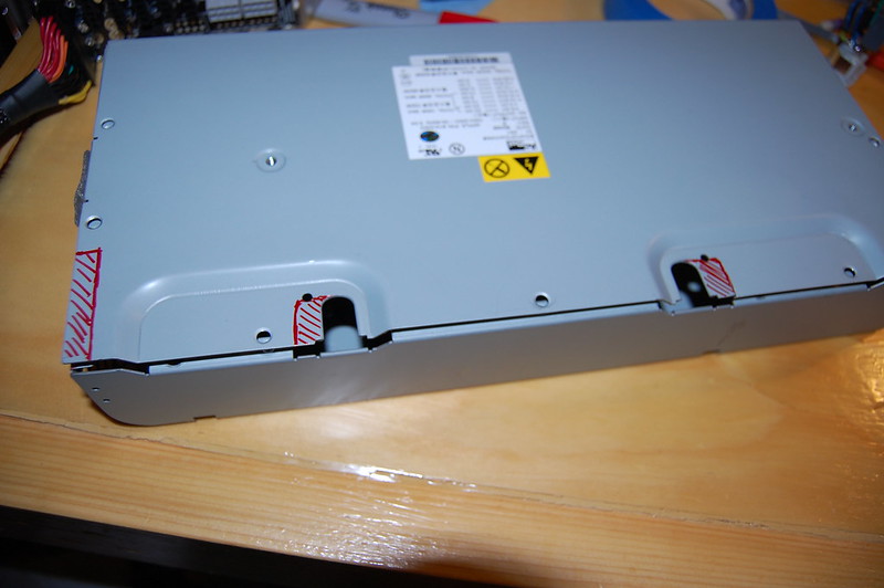
So here is the PSU removed from it's housing and the back panel cut so I could remove the switch and power connector.
7116971427_b4b72943e6_c.jpg


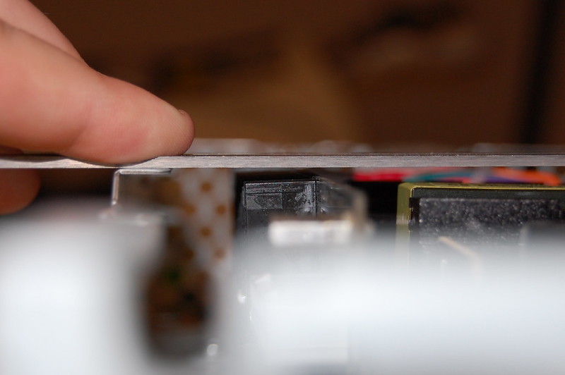
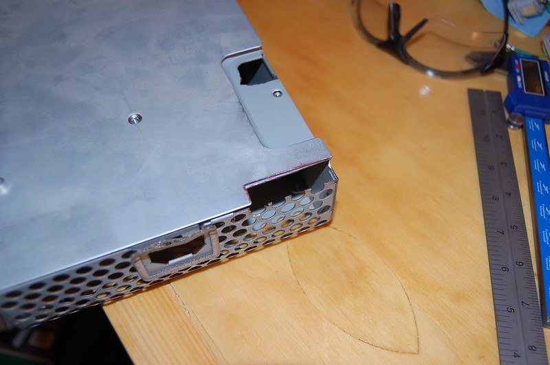
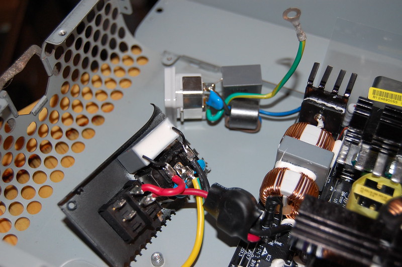
A closeup of the new power connector and the old. I really want to use the grey, so I need to find a way to mate these two, and I think I've found a solution. Unfortunately the part I need won't arrive for another week, so that step will have to wait.
6970895866_b8528a7e8b_c.jpg


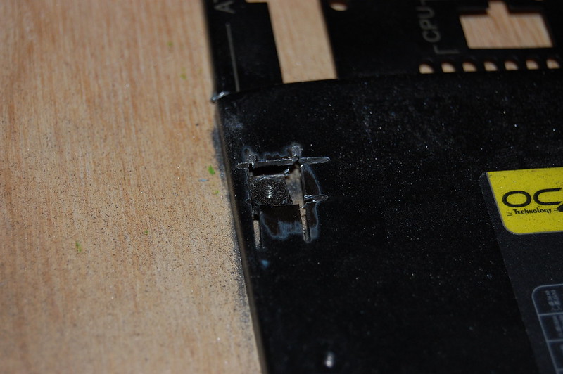
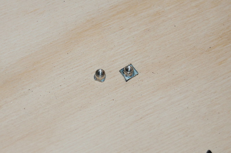
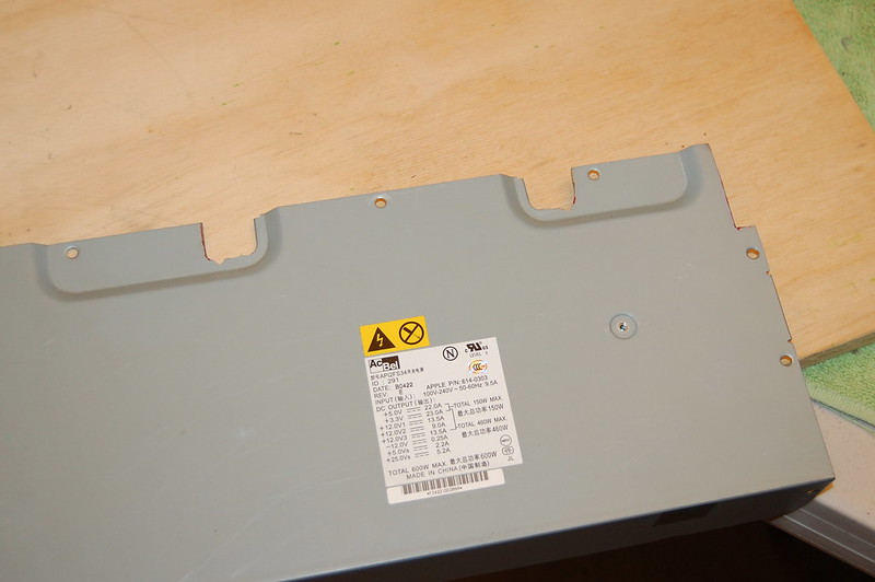
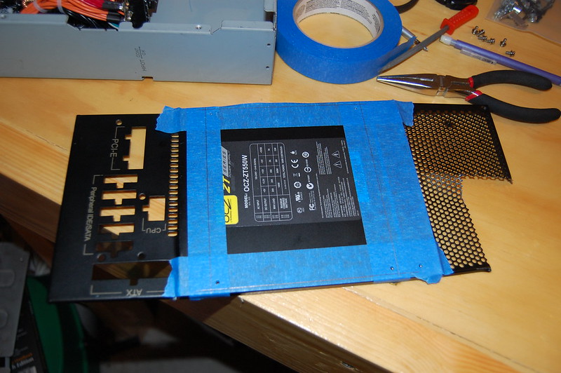
My original plan was to re-use the bottom plat of the OCZ PSU that has the PCB mounts on it. I would just attach the PCB to the bottom plate like it comes normally, and then attach that plate to the inside of the Apple PSU housing. However, (Sudds) and I are not sure it would give proper grounding to the PSU chassis, so my new plan is to remove the standoffs and then solder them to the Apple PSU enclosure. Either way, here was my lines drawn out to cut the bottom plate out, but I won't be doing that any longer. In a project like this, you have to adapt, and this is an example of that. Thought it would be worth mentioning and showing.
6970895632_12861a19ab_c.jpg


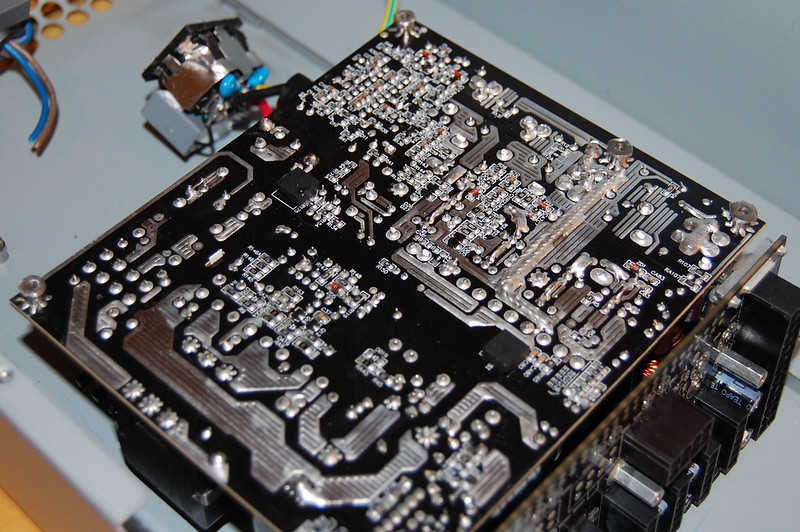
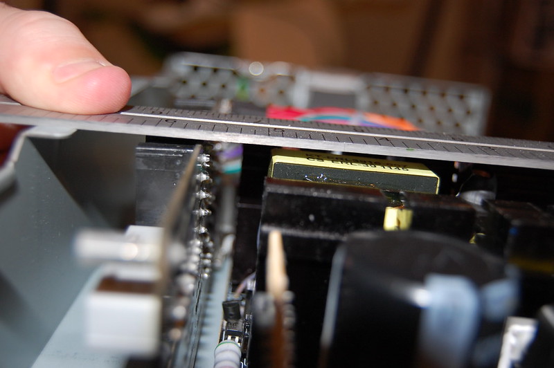
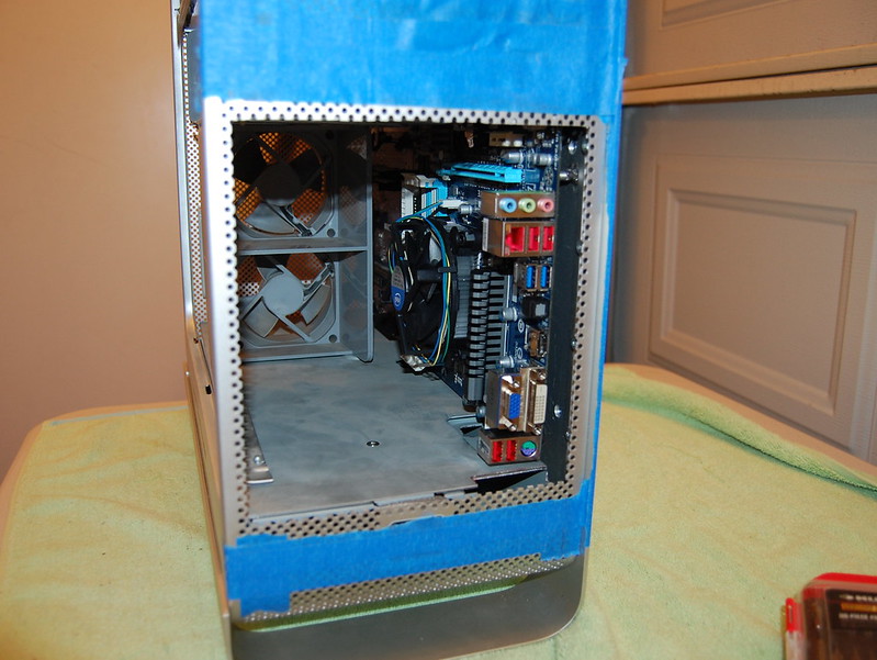
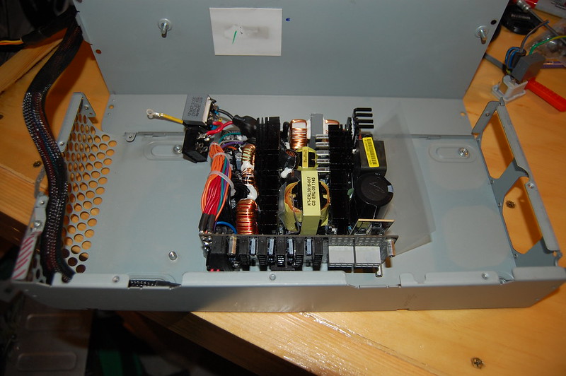
Here's the PSU with the connector and switch free, and placed inside the Apple enclosure. As you can see, I'm going to place the PSU sideways. The reason for this is because the modular mounting bracket in the front of my PSU is soldered pretty strongly to the board and will not move. My fear is that this would act as a wall/barrier to the air that the front fans would be pushing in it's direction. To avoid this, I'll place the PSU sideways. It will be a tight fit with the connectors on the PSU, but I could always cut out the side of the PSU enclosure if I really needed to, as there's actually room on that side of the PSU when it's inside the case.
7116972741_8f8d74561d_c.jpg


7116972927_e8b9e84e31_c.jpg


I'll want to make those holes a little bit bigger so that I can fit more cables through them should I need to.
6970897020_6d7d95f7c9_c.jpg


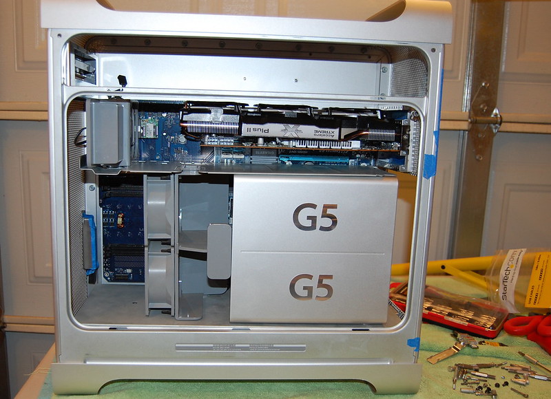
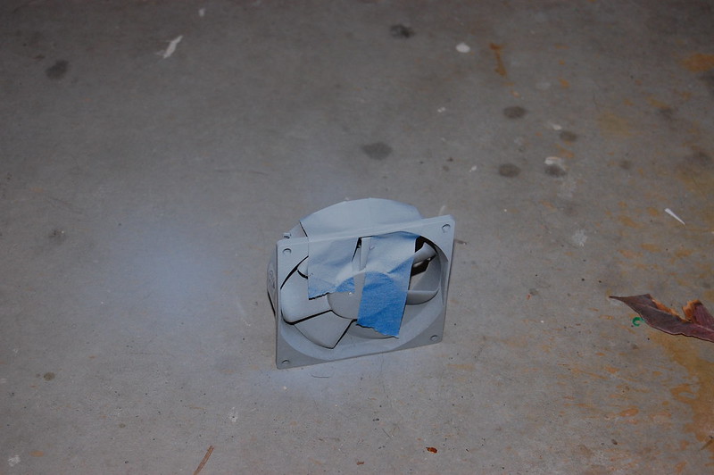
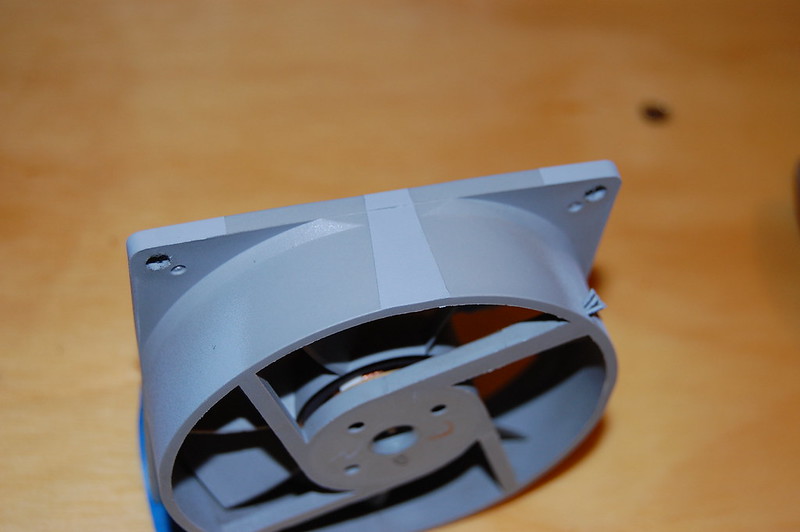
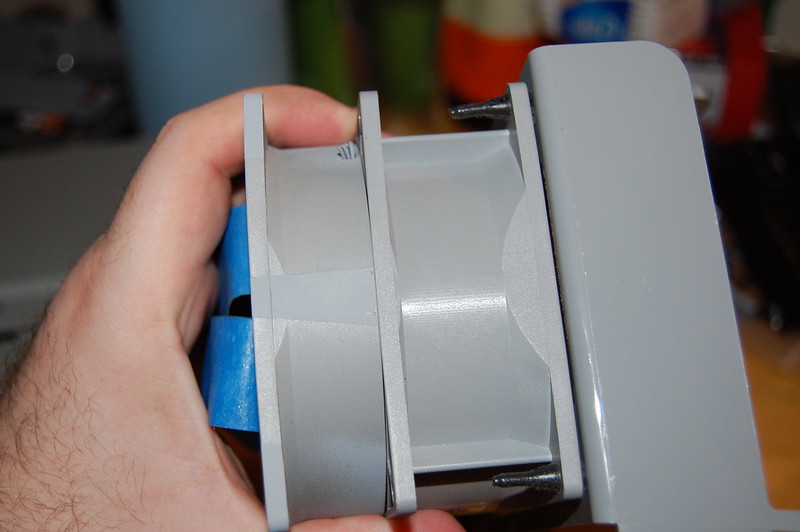
Okay, on to something different to give myself a break from the PSU. I spent the better part of the afternoon searching for a spray paint to match the grey of the internal plastic in the G5, such as the fans. I finally ran across a primer that I thought would do. I'll post up a picture of the can later if anyone is interested. Anyways, did a real quick test, and I'm pleased with the results. I only did a strip of paint on one of the fans just to give myself an idea. Of course it won't be identical, but the idea is to get it close so that it doesn't stand out. Here's a few pics.
6970896114_fcc0a3f74b_c.jpg


7116972373_0465002540_c.jpg


6970902876_48525d4fa3_c.jpg


Well, that's it for now. Time to head back to the garage for some more cutting...
 
nice work. G5 has a pretty generous space for placing PSUs.
beware of the heat sink, them seem pretty close to the cage.

Mac Pro 3.0, and 2009/2010 is much more restriction in comparison.
 
Airbus320 said:
nice work. G5 has a pretty generous space for placing PSUs.
beware of the heat sink, them seem pretty close to the cage.

Mac Pro 3.0, and 2009/2010 is much more restriction in comparison.

I plan to line the inside of the PSU with electrical tape or something similar as to avoid any interference like this. Thanks for the heads up though!
 
Vendetta said:
Airbus320 said:
nice work. G5 has a pretty generous space for placing PSUs.
beware of the heat sink, them seem pretty close to the cage.

Mac Pro 3.0, and 2009/2010 is much more restriction in comparison.

I plan to line the inside of the PSU with electrical tape or something similar as to avoid any interference like this. Thanks for the heads up though!

assure the tape are heat resisted. there are some adheasive heavy density foam that absorbs heat and transfers whilst insulating electrically.
 
Airbus320 said:
Vendetta said:
Airbus320 said:
nice work. G5 has a pretty generous space for placing PSUs.
beware of the heat sink, them seem pretty close to the cage.

Mac Pro 3.0, and 2009/2010 is much more restriction in comparison.

I plan to line the inside of the PSU with electrical tape or something similar as to avoid any interference like this. Thanks for the heads up though!

assure the tape are heat resisted. there are some adheasive heavy density foam that absorbs heat and transfers whilst insulating electrically.

Kapton tape is rated for extreme temperatures upwards of 500*F, so I hope that will do. :)
 
eelhead said:
Actually :

They have been used in applications at temperatures as low as -269°C (-452°F) and as high as 400°C (752°F).


:ugeek:

Touché. :geek:
 
Small update. I had a little bit of time to mess with the PSU. This is the bear in this project, so I'm in no hurry to tackle it in one go.

Time to remove the standoffs. Here I've removed the material from the underside of the standoffs, so that I can get a solid connection when I solder them to the Apple PSU enclosure.
7129672043_638bd56f39_c.jpg


Here's one cut out.
6983587286_a8bbff992b_c.jpg


And a little trimming and filing. Here's a before and after, with the after on the left.
7129672915_71fae88056_c.jpg


All five of the standoffs screwed into the PSU PCB.
6983588096_c67bf9c01f_c.jpg


With the standoffs added, not much clearance for this PSU. Here are two pics that show just how close it is.
6983588456_d64aceec84_c.jpg


7129673625_01e29f7608_c.jpg


Here's both plugs grounded. The goal is to connect these two.
6983589266_74261be188_c.jpg


Had to do a bit more cutting to make room for the motherboard I/O panel. Also made the opening bigger for the cable exits.
6983640846_5d5fa3c7c0_c.jpg


And all pieced together to make room for the I/O panel.
7129725627_cbaa48f99f_c.jpg


And that's about it for the PSU. I'm awaiting the arrival of the two 60mm fans that I'll mount as exhaust. I need them so that I can figure out the spacing between everything, which I want to get set before I solder these standoffs to the enclosure. Fans should be arriving soon.

The next thing I wanted to do (since I can't do anything else right now), is to put a few of the pieces together in the case, and see how it was coming together. I can't stress enough how important test fitting everything is. This image gives a good idea of what it will look like, but I also needed to figure out some of the cabling and how long I would need to make each power cable. Looks nice, but we still have a bit to go.
6983641364_90c5b01fe0_c.jpg


Here's an interesting view to see what it looks like behind the panel. Of course, I have an aftermarket cooler that will replace the stock Intel cooler.
7129726125_44d9539f7e_c.jpg


More later...
 
Nice work!

Can I make the suggestion to toss the stock G5 fans...?

I tried re-using them in my build, but even with under-volting them, they we're still way too loud. like jet turbine loud.

N.
 
Status
Not open for further replies.
Back
Top