Contribute
Register

Gigabyte Z490 Vision D (Thunderbolt 3) + i5-10400 + AMD RX 580

OK I also tried loading the install USB drive from the F12 menu, I got a second reboot, then the main screen screen to pick the boot disk, but then the NOT sign again. I did check to see if SecureBootModel to Disabled, and it is.
 

Hi Casey,

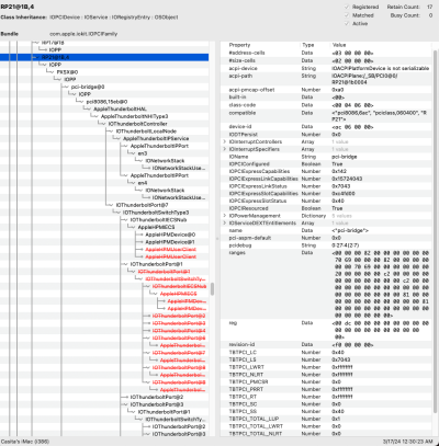
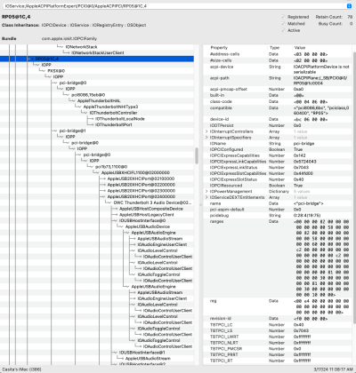
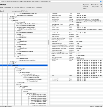
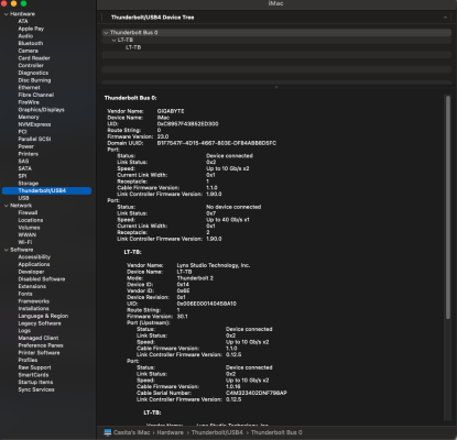
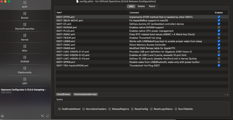
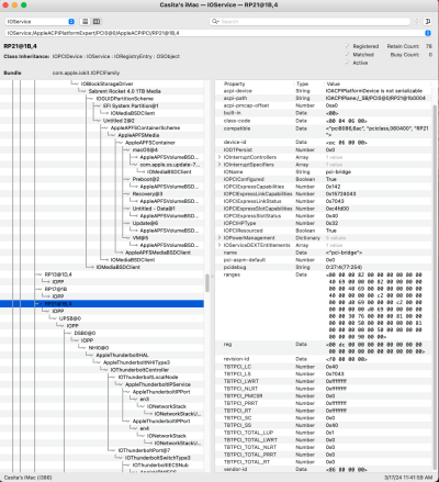
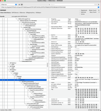
Back and trying to get Hot Plug to work on a flashed GC Titan Ridge card. I followed the above guide using Titan Ridge controller on Hackindrom to generate my SSDT, and no dice. I suspect it has to do with this RP05 and RP21 in my IOReg? I know I'm missing something. I'm not exactly sure how the port mapping works either if that could be a reason? Eventually I stole the attached SSDT-DTPG from a post you made helping someone else, as my original file from open core wasn't working. I am unsure if those are unique or need to be written to match each system.

Believe I'm on open core 0.9.8, BTW.

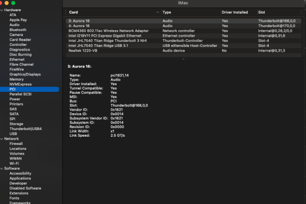
Hot swap works fine most of the time on this motherboard's built in TB, but I'm trying to get this Titan Ridge card to work so I can use it in my other z490 board with the broken TB controller (if you remember my posts a couple months back). I figured I'd test it in this working Mobo first, before I swap the card and my machine back to the other board. Let me know if that is a bad idea, and I should try it in the other machine first. Just didn't want to switch machines yet in case this Titan Ridge card was bad or something.

Also any idea how to get my monitor to display, after waking from sleep? Currently, I have to turn it off and then back on to get it to display connected via HDMI. Otherwise the machine is working great.

For me that means Protools and Ableton 11 running with 2 Lynx Aurora 16's daisy chained through the lynx LT-TB cards.

Thanks in advance for all your help. I wouldn't be here without you and the community.


-- Edit -


Wow I'm dumb. Found the proper guide for the hackindrom. Followed it by switching the RP05 edit back to RP21. I have hot plug on the GC Titan Ridge 2.0 now. Unfortunately, it did break hot plug on the built in controller. I tried changing the bus ID from 0 to 01, but no dice, it might not matter to me as I'm going to try the card in my other board with the broken TB controller. I am curious though what I would need to do to make both the internal and PCIe controllers work in case this card doesn't work on my other motherboard, and I come back to this one. I'm trying to understand this stuff, but seems like I'm always missing pieces and mostly the "why" of everything.
 

Attachments

  • SSDT-DTPG.aml
    100 bytes · Views: 1
  • SSDT-TB3-HackinDROM.aml
    2.2 KB · Views: 2
  • SSDT-TB3HP.aml
    2.1 KB · Views: 2
  • victoroni - IO reg.png
    victoroni - IO reg.png
    303 KB · Views: 6
  • Victoroni - IOReg .png
    Victoroni - IOReg .png
    284.4 KB · Views: 5
  • openconfig j.png
    openconfig j.png
    188.8 KB · Views: 6
Last edited:
SSDT-DTPG is generic.
With multiple Thunderbolt controllers, they should be on different buses.
Each controller should have its own SSDT set to the proper path. Both of your SSDTs point to RP05, and, as shown by IOReg screen shots, there are multiple unnamed bridges so none is attaching properly.
"RP05" or "RP21" are not arbitrary values which you set by "following a guide": These must match your hardware, that is not only your motherboard but the exact slot the card is in.
 
@victoroni,

You may have set up everything correctly. Let’s take a look at the latest IOReg screenshots for both controllers (on the test machine and/or on the actual target machine).

Let’s also take a look at screenshot of “System Information -> Thunderbolt/USB4”.

Thunderbolt Bus ID and UID should be different for each controller.
 
If you are using Intel WiFi then:
  • If you are installing Sonoma 14.0 through 14.3, it's necessary to use the 14.0 build of AirportItlwm
  • If you are installing Sonoma 14.4, it's necessary to use 14.4 build of AirportItlwm
... otherwise a boot loop will occur.
Thanks again.

I have done as you suggested. Unfortunately, I am still getting a reboot loop when I select macOS Installer from the Boot Picker Menu.
 
Thanks again.

I have done as you suggested. Unfortunately, I am still getting a reboot loop when I select macOS Installer from the Boot Picker Menu.
If you see a boot option called macOS Installer, it's likely from a previously started upgrade that did not succeed. So we should boot into macOS itself and start the upgrade again. The existing "macOS Installer" will then be replaced with a new one.
 
SSDT-DTPG is generic.
With multiple Thunderbolt controllers, they should be on different buses.
Each controller should have its own SSDT set to the proper path. Both of your SSDTs point to RP05, and, as shown by IOReg screen shots, there are multiple unnamed bridges so none is attaching properly.
"RP05" or "RP21" are not arbitrary values which you set by "following a guide": These must match your hardware, that is not only your motherboard but the exact slot the card is in.

Thanks for the reply. Unfortunately I've never done this before and am a bit green when it comes to hackintoshing, so the easiest thing for me to do is follow Casey's guides which have led to success so far. I believe the new HackinDrom SSDT I made is pointing back to RP21 and that is what fixed the titan ridge card. I'm still not exactly sure how to name/assign the bus's/ports or bridges, i see the customize function in HackinDrom and attempted to add a number but I guess that's not correct.

Also not sure what I'm looking at in IOReg like where to check the existing mappings and naming structures. Without access to this knowledge I've been trying to learn from Casey's guides which generally have my exact machine specs until I can learn the why and how. If you can point me to the information I need to help understand these concepts I am happy to attempt to learn.

Lastly: According to the GC Titan Ridge compatibility chart: "Z490 series
(Support by PCH PCIe x4 slot only)" so i put the card in the PCIe x4 slot which is the 4th or bottom slot on the motherboard. So I'm not sure what that means as far as naming the correct bridges or how to find that info once again.

@victoroni,

Let’s also take a look at screenshot of “System Information -> Thunderbolt/USB4”.

Thunderbolt Bus ID and UID should be different for each controller.

Still on the test machine, and it looks like the Thunderbolt section only shows one controller, the motherboard controller is not flashed so i assumed that is normal, but let me know. I would like to understand this for future attempts/builds. Is the naming of ports and bridges similar to the USB mappings? I still haven't dived in to that as everything seems to be working fine.

Hopefully this is the correct screen shots of the current IOReg, would be easier to upload the file but my serial is in there not sure how to remove it.

Based on what etorix said about each controller having it's own ssdt, would enabling the stock Opencore ssdt-TB3hp as well possibly implement hot plug for the Mobo controller? I assumed i was supposed to only use one and therefore disabled it.
 

Attachments

  • SSDT-TB3-HackinDROM.aml
    2.2 KB · Views: 1
  • RP05.png
    RP05.png
    235.3 KB · Views: 8
  • Rp05 PXSX@0.png
    Rp05 [email protected]
    206.3 KB · Views: 7
  • PCI.png
    PCI.png
    132.7 KB · Views: 8
  • Thunderbolt:USB4.png
    Thunderbolt:USB4.png
    193.4 KB · Views: 6
  • Screenshot 2024-03-17 at 12.16.24 PM.png
    Screenshot 2024-03-17 at 12.16.24 PM.png
    200.2 KB · Views: 6
  • RP 21 .2.png
    RP 21 .2.png
    248.3 KB · Views: 7
  • RP21 NHI0@0.png
    RP21 [email protected]
    255.9 KB · Views: 6
@victoroni,

The screenshot for RP05 and RP21 both show that Thunderbolt Bus is enabled. Are both screenshots from the same test computer?

If so, please enable the SSDT shown below and reboot. Then post the entire IOReg file.

We can address your questions after this.

Screenshot 2024-03-17 at 12.16.24 PM.png
 
Also not sure what I'm looking at in IOReg like where to check the existing mappings and naming structures.
You have found your controllers though.
1710713241322.png

Reading only the "real" element (those which have an address after '@'), and knowing that the base is the System Bus, this translates to:
ACPI: _SB.PCI0.RP05
PCI: PciRoot(0x0)/Pci(0x0,0x0)/Pci(0x1C,0x4)

Still on the test machine, and it looks like the Thunderbolt section only shows one controller, the motherboard controller is not flashed so i assumed that is normal, but let me know.
Look also under PCI, as macOS may not identify the controler under Thunderbolt.
Is the naming of ports and bridges similar to the USB mappings?
No, it's nothing like USB. Naming the PCI bridges is done by the SSDT, if it loads properly. Seeing 'pci-bridge@0' instead of 'UPSB', 'DSB0', 'NHI0' and others is merely a sign that the SSDT is not loading properly and the user's job is only to point the SSDT to the correct place by editing the 'External' and 'Scope' declarations in the first lines of the SSDT.

Hopefully this is the correct screen shots of the current IOReg, would be easier to upload the file but my serial is in there not sure how to remove it.
There's indeed a lot of information in an IOReg file, but you might be the first to worry about it. Guidelines are to edit out the serial number out of config.plist before posting an EFI but nothing is said or done about IOReg. Admittedly, an IOReg is not a working EFI and cannot be used as such to boot a hack.

Based on what etorix said about each controller having it's own ssdt, would enabling the stock Opencore ssdt-TB3hp as well possibly implement hot plug for the Mobo controller? I assumed i was supposed to only use one and therefore disabled it.
I leave the rest to @CaseySJ, but yes each controller needs its own piece of ACPI code, which in practice means one SSDT per controller. (One could put all the code in one SSDT but that would only make maintenance more difficult.)
 
Last edited:
If you see a boot option called macOS Installer, it's likely from a previously started upgrade that did not succeed. So we should boot into macOS itself and start the upgrade again. The existing "macOS Installer" will then be replaced with a new one.
Thanks,

Unfortunately I still have the same problem after many attempts.

Perhaps I should try a fresh install to a new SSD from USB stick.
 
Back
Top