Contribute
Register

neilhart's TR - ASUS Terminator Revisited

Status
Not open for further replies.

neilhart

Moderator
Joined
May 25, 2010
Messages
2,686
Motherboard
ASRock Fatal1ty Z270 Gaming - ITX/ac
CPU
i7-7700T
Graphics
GTX960
Mac
  1. MacBook
  2. MacBook Pro
Mobile Phone
  1. iOS
“Too much stuff…” I live in clutter most of the time because the current project always takes too long and bits for my next projects have to be collected and stored until needed;… “Too much stuff”.

In 2004 one of my hot projects was building out the ASUS T2-P Terminator (bare bones Pentium 4 system). At the time this was bleeding edge PC tech. Our system got passed around in the family and finally came back to me a year ago.

P_500.jpg


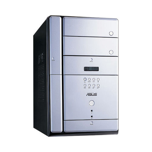
More at: http://www.asus.com/Desktops/T2P_Deluxe/

The system ran Win XP Pro but was of no interest to anyone any longer so I set about putting it out for the e-waste pickup. I changed my mind and stripped the system retaining the case and several bits (sub-assemblies). The motherboard, AGP video card and IDE optical drives went into the e-waste.

I stacked the bits back inside of the case and set the top cover back onto the case frame. I then proceeded to step around the derelict thing for several weeks as I went onto new projects.

Over the next few days I will share photos and the details of this “Terminator Revisited” project.

I have been out of work for about six months so my “keep busy” projects are intended to be low cost (little or no additional outlay). The TR is an example of what a tech pack rat can accomplish given the motivation.

More to follow.

Good modding,
neil
 
The final TR is made up of the following:

1. The case framework.

2. The internal right side motherboard mount.

3. The rear plate with I/O, PCI slots and PSU mounting.

4. The front panel with power switch, LEDs, and USB and audio ports.

5. The cover (right, top and left sides).

The case framework:

As seen here, the case framework has been reduced to a minimum.

Frame1.jpg


Frame2.jpg


Frame3.jpg


I removed the rear panel using the dremel and cutting disk leaving only the existing top and side cover mounting hole land areas. The wrap around lip is fairly small, say about 3 to 6 mm.

Also note that I added top and bottom 120 mm fan mounts. I added two holes for mounting the BitFenix front panel USB and Audio port assembly to the upper front left vertical.

I am reusing the original plastic feet at this time. These feet are approximately 6 mm tall and I would like to have twice that. The lower fan is an exhaust and taller feet would tend to improve the air flow.

More to follow.

Good modding,
neil
 
The internal right side motherboard mount.

MB-tray-1.jpg


Seen on the right in this photo is the original T2-P motherboard tray. On the left side is my version that accepts a Micro ATX motherboard. The original motherboard was a larger then Mini-ITX but smaller then Micro ATX.

I wanted the motherboard to be set out from the mounting plate about 3/4 inch. I selected 8 standoffs from past G5 PM case hacks and drilled through the each. This retained the threads at the top and I threaded the lower portion with a 6-32 power drill tap.

MB-tray-2.jpg


The standoffs are mounted with 6-32x1/4 inch stainless flat head hex screws. The odd shape of the plate is to act as a brace for the case (it contacts the frame on all four edges) and to provide clearance for the cover locating flanges.

MB-tray-3.jpg


MB-tray-5.jpg


MB-tray-6.jpg


I am using a Gigabyte P55M-UD2 motherboard and a i7-860 with 12 GB DDR3 memory seen here. These parts are from previous projects that I had decommissioned and were part of the clutter in my home lab/office.

The CPU cooler is a Zalman unit that I had laying around. I was not happy with the three wire fan and I kludged in a 4 wire Intel fan and now PWM fan control works.

More to follow.

Good modding,
neil
 
The rear plate with I/O, PCI slots and PSU mounting.

The rear plate started life as a top panel on an Apple G5 Power Mac and was laying in my salvage bin.

I used my 10” table saw and removed the flanges and cut the plate to size.

With the motherboard standing on the standoffs on the motherboard mounting plate I located the motherboard side to side and top to bottom. This allowed me to cut the I/O panel hole in the rear plate.

RP-1.jpg


I then could locate the correct motherboard location front to back and proceeded to drill and countersink the holes for the MB standoffs.

With the MB mounted I proceeded to locate the PSU mounting followed by the PCI slots.

RP-2.jpg


RP-3.jpg


The PCI slot graft is from the G5 PM salvage bin.

I elected to add the Apple mesh hole pattern.

RP-4.jpg


RP-5.jpg


Too many holes and too much time. However the panel is the original anodize and not painted.

More to follow.

Good modding,
neil
 
The front panel with power switch, LEDs, and USB and audio ports.

The original front panel had some damage to the plastic and just too many details that I was not going to use.

FP-1.jpg


I retained the power switch, power LED and drive activity LED in the original locations. Then I added the BitFenix “USB 3.0 Upgrade Kit” to the upper left front. I should note that this motherboard is pre-USB3.0 and the front panel USB3 port cables are tie-wrapped aside for now.

FP-2.jpg


I started by disassembling the original panel removing all of the silver pieces. This left a black ABS bezel which I used my power sander to remove the much of the mounting details for the silver pieces. Using Power Mac top panel from my scrap bin, I cut out a plain full cover for the bezel adding holes for the controls and the USB panel.

FP-3.jpg


The cover (right, top and left sides).

I found that the system needed more air to be able to run my one hour stress test and have the temps stay below 70 C. With the top in-take and the bottom exhaust fan setup the closed system now runs Prime95 with a max temp of 67C.

So I resorted to remedial methods to cut round hole for the 120 mm fan.

top1.jpg


top2.jpg


And then I decided that a side window would add some interest so I went ahead and cut that hole also.

TC-Win1.jpg


TC-Win2.jpg


TC-Win3.jpg


The cover has the original paint and shows wear and tear of the 10 years. I resisted the urge to repaint it.

More to follow.

Good modding,
neil
 
What kind of tool are you using to drill those holes so nicely, I was looking forward to create a special mesh to protect the fan on my mod but using a drill was a disaster.

PmLondon I use a floor standing drill press. The key here is using a piece of mesh as a drill guide where the guide is held to the work piece securely by screws and nuts.

Good modding,
neil
 
Final - Terminator Revisited

The system is up an running with the Gigabyte P55M-UD2 and i7-860 for now.

I will upgrade the motherboard to a MSI Z87M-43 and the CPU to a i7-4770K one of these days. This would be to see how far I can overclock that configuration with this set of fans.

And I may add a few LEDs with a controller and touch switch.

X7.jpg


X5.jpg


X3.jpg


Comments and questions are welcome.

Good modding,
neil
 
PmLondon I use a floor standing drill press. The key here is using a piece of mesh as a drill guide where the guide is held to the work piece securely by screws and nuts.

Good modding,
neil

By a floor standing drill press I wonder if something smaller would work :

10698.jpg
 
By a floor standing drill press I wonder if something smaller would work :

View attachment 93862

Yes this would work as long as the work piece is small enough to fit on the table. The important dimension is the drill center line to the nearest point of the upright (that is about 21 cm on my unit). The floor standing drill press has the added ability to accept really tall work pieces.

Good modding,
neil
 
Status
Not open for further replies.
Back
Top