Contribute
Register

Yet Another NUC iMac G4

Status
Not open for further replies.
Did you use 3.3v for both vedid and vcc?
 
Yes, 3.3V on both.
At first I connected grey, purple, green to ground and blue, orange, yellow, pink (VEDID) to 3.3V. But the PSU did not start. Then I measured the resistance between the wires, and it turned out purple is connected to yellow/orange and blue is connected to ground - so I made a short circuit there.
Then I swapped these wires. PSU started this time but no picture. I decided to disassemble the LCD, and measure the pinout. Purple 3.3V and blue GND confirmed, and also double-checked the black cable.
Now I don't know what to do besides I started to look for a replacement LCD... ;)
 
I toasted a 17" G4 LCD a few projects back. It sucked. Took my PicoPSU with it, unfortunately. A costly mistake by the time it was all fixed. Perhaps look for an old iMac G5 17" on Craigslist. I think the LCD's are directly pin compatible with the G4 and theres typically lots of them around in decent shape.

Good Luck...


Ersterhernd
 
The project slowed down a little bit as i'm still waiting for some parts to arrive :cry:
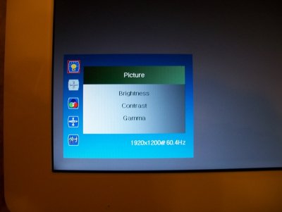
As I already mentioned the original LCD panel is dead, and instead of ordering a replacement (which is rather expensive I think) I decided to get an LM171WU1 panel which has higher resolution: 1920x1200.
I already installed, and have it running:
100_2902.JPG100_2903.JPG
(sorry about the blurry images :crazy:)
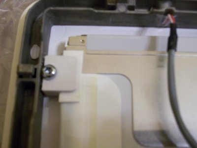
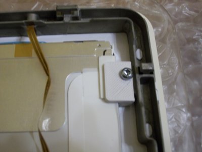
I had to cut some metal parts off the panel around the edges with dremel and 3d printed some small plastics to secure the screen in the bezel with the original screws/holes:
100_2904.JPG100_2906.JPG
I put some foam stripes under the plastic to ease the stress it may cause on the back of the panel.
Unfortunately the inverter of this panel cannot fit inside the screen housing and also waiting for another (longer) LVDS cable. I don't know if it's okay to route the high-voltage inverter wires together with the data cables in the neck, but will give it a try... :think: Originally I wanted to have the screen controller and the inverter at the back of the panel, then only an HDMI and power source cables should run in the neck...
That's all the progress I have since my last report :rolleyes:
 
Neck re-wiring

Finally all the connectors and cables arrived for my iMac :D or so I tought :lol:
(made only a few pics in the process and sorry about the quality - as usual)

As I already mentioned I decided to replace the dead screen with a different one: an LP171WU1, same size but different resolution and different fixing. The inverter of the new screen could not fit into the lcd housing and the LVDS pinout/wires are way different from the original, so I had to re-wire the neck.

Taking apart of the neck is not that dangerous as you may think, it will not explode, will not cut your fingers or such. To remove the special, 3 dot screws I used two torx/hex bits. It's kinda loose, very easy to remove by hand. It's worth to remember this when tightening - over tightening will damage the plastic washers.
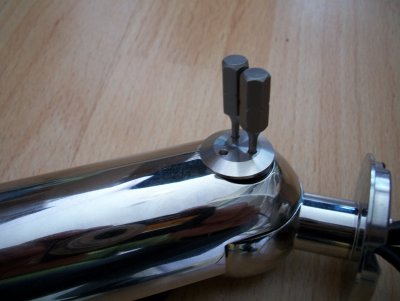
100_2981i.jpg

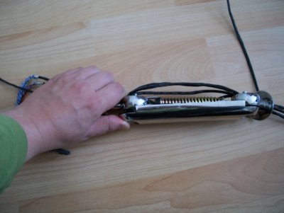
When all the screws are out, it's time to separate the covers. One end of the neck will pop out of place anyway (disassembled it a few times and never could get apart it without) you can use a small flat screwdriver to separate the sides. The shafts will pop out of place as the spring is pulling it. Scary at first but you cannot put your fingers inside yet so...
100_2980i.jpg
I made no pics of how I removed the cables (basically removed the connectors from one end and pulled out) but on the above picture you can see the spring is pulling about 2cms.
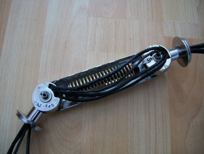
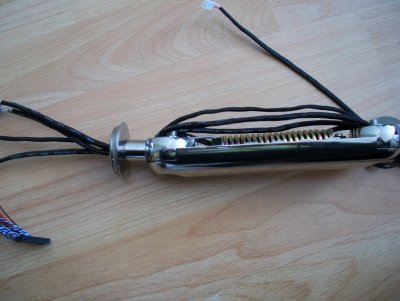
100_2976i.jpg100_2978i.jpg
I ordered two pieces of 80cm LVDS cables (with different pinout again) and used the wires from one to the other. The pins of the FI-X connector can be pulled out of place by carefully raising the plastic above it (used a small needle - but anything will do with a sharp end).

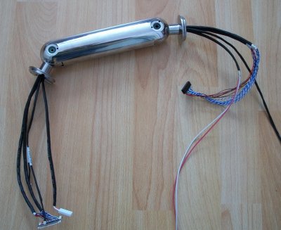
So... I prepared the cables: the led/mic, the inverter and the lvds (which I separated into two for easier routing, together it would be too stiff). Wrapped with aluminium tape for EMI shield (will ground one end), shrink tubed, and put into the neck. It's a tight fit but not that difficult. All-in-all took about 2 hours.
100_2974i.jpg

About assembly: It's fairly easy to put back in place one of the ends. Then the other end will be about 2cms away from the original position. I used a big screwdriver between the end of the spring (there's a black plastic on it) and the steel joint. Pushed the screwdriver with one hand and the joint with the other. When it's in place it will non pop out if you are careful.

And the bad news again: one side of the screen is darker :thumbdown: So this long cable for the inverter (on the high voltage side) is not good (or the inverter is weak). I exprimented with different cable lengths, and the longer the cable is, makes darker the backlight. At some length it gets totally dimmed.

Anyway now I will try to get a different inverter for the screen that may fit into the case. If anyone have ideas what to try I will gladly do. At the moment I use my hackintosh without the neck.
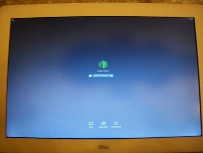
 
Good to see, that this project ist still alive! :thumbup:

So this long cable for the inverter (on the high voltage side) is not good (or the inverter is weak).

Did you use proper high voltage capable wires? I think the original inverter cables have a special silicone insulation.

MacTester
 
I also noticed a bit of darkness on the left side of the screen with the original ~15cm wire for the inverter. :confused: It's easier to notice in dark room... not a big thing but...
So it's either an issue with the inverter or the CCFL backlight :(
 
Status
Not open for further replies.
Back
Top