- Joined
- May 27, 2010
- Messages
- 2,364
- Motherboard
- Dell Optiplex 9030 All in One
- CPU
- i5-4690K
- Graphics
- HD 4600
- Mac
- Classic Mac
- Mobile Phone
Background
This follows on from my scratch build Mini ITX http://www.tonymacx86.com/others/87637-high-power-mini-itx-scratch-build.html and in many ways, this build is only going ahead because I had a lot of the components sitting here already.
Bits being re-used from the scratch build are:
Zotac Z77 wifi board ,
Corsair RAM,
mSATA drive
Parts re-used from earlier Cube mod.s
160W PicoPSU, Old Cube casings and bits.
New parts: i7 3770k and 500GB SSD (Big investment!!)
I'll admit this is a bit of a silly power crazed build. Having done a Cube with an i5 2500K I wanted to up the Geekbench scores and see whether the unused H80 I have sitting around here could be used in a Cube and could keep an i7 3770k cool with a mild overclock.
Before doing the tear down of my scratch build I removed my good old i5 2500k from it, put in the i7 3770k and changed a few kexts, DSDT and put in the PicoPSU to see how my combination of components would work from a power eating view.
The power from the wall, when geek benching and stress testing with a mild overclock (to 4GHZ on turbo and with a 1.2 Vcore - haven't tried to lower that yet) gave a maximum peak power draw while stressing and watching TV through my EYETV dongle and web browsing of 120W at the 4GHz turbo boost settings. I consider that there is no point trying to go more than that with a picosupply.
Maximum CPU temps in my open case during the stress testing topped out at 77C using my custom cooler and motherboard temps stayed at a low 28C but I do not know yet if a modified H80 will cope (that comes later) and if it will cope in the modified Cube.
Ceasing stress testing reduces Watts from the wall to 45W (as my i7 is only set for a higher turbo boost and not overclocked for normal tasks. Five minutes after the stress tests stopped CPU temp.s settled at 35C).
The benchmarks under Geekbench come in at 14,500 at these settings.
So.... so much for the system I'll be trying to transplant and on to the case mod.
Before starting the case mod I looked around for any existing water cooled cubes and all I could find was this single photo:

I couldn't find anything with the Cube boxed up, and I gather this was a mod of 2004 from Boris Jotic who was water cooling his original upgraded Cube.
So I am pretty sure no-one else has done yet what I want to try - which is to have the loop inside the case. If anyone has done that already then please let me know as I'd like to take a look!
The build
First things to do were to check the Itx board and H80 block would fit on the "thin" side of the Cube case (Cube internals are asymmetrical and challenging….):

So, the dummy board would fit, and there is about 2mm of clearance between the integrated block/pump and the central handle latch mechanism.
Next check is to see how the radiator might mount in the case. I came up with this:


What you see here is the radiator mounted to the original CD drive holder and, to the right of the second picture a 120mm fan that sits where the original Cube hard disk would have been. This holder makes a nice frame to hold the radiator and fan combo.
As a first fit I was happy that this would be a good place for rad mounting and with a bit of luck just the one 120 fan might do the job if I can get a good air flow in from top and bottom of the Cube. If I am not so lucky I can put another 120 fan on the outside at the back of the Cube and make it removeable.
As the radiator would be against a solid wall inside the Mac inner case, the next thing needed is to cut it:

No laser cutting here, just good old dremeling - this case eats dremel disks!!! The discolouring is as this particular old case originally had my old Mini in a Cube mod inside it that my wife has had for a number of years. It was re-sprayed white at one stage and after being knocked about by me it now needs stripping and painting again. This great big hole is for the radiator to expel heat out the back of the Cube - the plan being that from the front view the Cube looks pretty much normal. The same Cube case had a cut down casing and was used on its side. This case will probably not be the final outer case, but I cut it up for practice too:

This part did have the hole laser cut in it, but surprisingly it turned out the acrylic used by Apple was of a fairly poor quality (in my opinion). This type of acrylic is a bit unpleasant to laser cut as it is quite soft and the edges instead of taking on the lovely flame polished effect that is acheved with good quality acrylic, it bubbled at the edges and was quite smelly to cut. I'll have to get out the wet and dry and my polishes and work on the cut edge to make it more presentable.
In a real Cube the drive cage is normally front mounted and I want to move it to the back so I needed to make some more changes to the inner case and the can that surrounds it.
The logo for the Cube touchswitch is towards the rear of the acrylic case, and the actual switch is located to be above the motherboard area on the original Cube. That configuration does not work for me though as I really do not want the switch above the mobo as space there is tight and I'd prefer it above the radiator where there is some space.
This combination of factors and my rear facing radiator meant I needed to effectively spin the Cube, re-locate the switch on the inner Cube cage and then cut a new hole for it on the outer part. 
So the next job was cutting another hole for the touch switch on the inner cage and making some fixings for it -using my favourite thing of the moment rivet nuts.

Here, the new hole is at the top. I then needed to do the same thing to the metal can part:
 

The hole was cut using a hole saw and turned out better than I had hoped (one slip costs a lot of time!).
Next job to cut the tubes from the H80 - as there was no way it would fit with the long pipes - and drained the fluid.

The pipes have an ID of 6mm and an OD of 8mm, so the plan is to rejoin the loop with hose of the right dimensions and lengths. This is about where I am and my current challenges are: (1) find a way to make the pipes turn in the right places without kinking - so have some springs and guides on order. (2) Find a way to get the loop closed again without it being full of air.
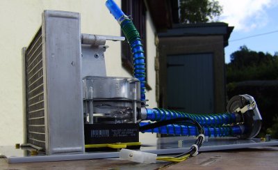
I have done some experimenting to see how I can get the loop closed again and so far it is frustrating. If all else fails I may have to resort to an external reservoir mounted behind the perspex case, but in the meantime I am trying: loop filling under water; trying to remove air and inject water with syringes. Both have been very frustrating.
The next try will be to put a temporary extra Laing DDC with a pump top reservoir in the loop and run the loop until I get all air into the reservoir and then try and do a tube swap underwater.
I'll post more as this project gradually comes together. I'm currently waiting my antikink springs and tube directors from OC UK as well as some 6mm G1/4 barbs to try out my theories with the Laing pump combo.
We shall see...In the meantime any suggestions as to how to avoid my fall back of an external tube reservoir mounted to the Cube back are greatly appreciated!
This follows on from my scratch build Mini ITX http://www.tonymacx86.com/others/87637-high-power-mini-itx-scratch-build.html and in many ways, this build is only going ahead because I had a lot of the components sitting here already.
Bits being re-used from the scratch build are:
Zotac Z77 wifi board ,
Corsair RAM,
mSATA drive
Parts re-used from earlier Cube mod.s
160W PicoPSU, Old Cube casings and bits.
New parts: i7 3770k and 500GB SSD (Big investment!!)
I'll admit this is a bit of a silly power crazed build. Having done a Cube with an i5 2500K I wanted to up the Geekbench scores and see whether the unused H80 I have sitting around here could be used in a Cube and could keep an i7 3770k cool with a mild overclock.
Before doing the tear down of my scratch build I removed my good old i5 2500k from it, put in the i7 3770k and changed a few kexts, DSDT and put in the PicoPSU to see how my combination of components would work from a power eating view.
The power from the wall, when geek benching and stress testing with a mild overclock (to 4GHZ on turbo and with a 1.2 Vcore - haven't tried to lower that yet) gave a maximum peak power draw while stressing and watching TV through my EYETV dongle and web browsing of 120W at the 4GHz turbo boost settings. I consider that there is no point trying to go more than that with a picosupply.
Maximum CPU temps in my open case during the stress testing topped out at 77C using my custom cooler and motherboard temps stayed at a low 28C but I do not know yet if a modified H80 will cope (that comes later) and if it will cope in the modified Cube.
Ceasing stress testing reduces Watts from the wall to 45W (as my i7 is only set for a higher turbo boost and not overclocked for normal tasks. Five minutes after the stress tests stopped CPU temp.s settled at 35C).
The benchmarks under Geekbench come in at 14,500 at these settings.
So.... so much for the system I'll be trying to transplant and on to the case mod.
Before starting the case mod I looked around for any existing water cooled cubes and all I could find was this single photo:
I couldn't find anything with the Cube boxed up, and I gather this was a mod of 2004 from Boris Jotic who was water cooling his original upgraded Cube.
So I am pretty sure no-one else has done yet what I want to try - which is to have the loop inside the case. If anyone has done that already then please let me know as I'd like to take a look!
The build
First things to do were to check the Itx board and H80 block would fit on the "thin" side of the Cube case (Cube internals are asymmetrical and challenging….):
So, the dummy board would fit, and there is about 2mm of clearance between the integrated block/pump and the central handle latch mechanism.
Next check is to see how the radiator might mount in the case. I came up with this:
What you see here is the radiator mounted to the original CD drive holder and, to the right of the second picture a 120mm fan that sits where the original Cube hard disk would have been. This holder makes a nice frame to hold the radiator and fan combo.
As a first fit I was happy that this would be a good place for rad mounting and with a bit of luck just the one 120 fan might do the job if I can get a good air flow in from top and bottom of the Cube. If I am not so lucky I can put another 120 fan on the outside at the back of the Cube and make it removeable.
As the radiator would be against a solid wall inside the Mac inner case, the next thing needed is to cut it:
No laser cutting here, just good old dremeling - this case eats dremel disks!!! The discolouring is as this particular old case originally had my old Mini in a Cube mod inside it that my wife has had for a number of years. It was re-sprayed white at one stage and after being knocked about by me it now needs stripping and painting again. This great big hole is for the radiator to expel heat out the back of the Cube - the plan being that from the front view the Cube looks pretty much normal. The same Cube case had a cut down casing and was used on its side. This case will probably not be the final outer case, but I cut it up for practice too:
This part did have the hole laser cut in it, but surprisingly it turned out the acrylic used by Apple was of a fairly poor quality (in my opinion). This type of acrylic is a bit unpleasant to laser cut as it is quite soft and the edges instead of taking on the lovely flame polished effect that is acheved with good quality acrylic, it bubbled at the edges and was quite smelly to cut. I'll have to get out the wet and dry and my polishes and work on the cut edge to make it more presentable.
In a real Cube the drive cage is normally front mounted and I want to move it to the back so I needed to make some more changes to the inner case and the can that surrounds it.
The logo for the Cube touchswitch is towards the rear of the acrylic case, and the actual switch is located to be above the motherboard area on the original Cube. That configuration does not work for me though as I really do not want the switch above the mobo as space there is tight and I'd prefer it above the radiator where there is some space.
This combination of factors and my rear facing radiator meant I needed to effectively spin the Cube, re-locate the switch on the inner Cube cage and then cut a new hole for it on the outer part. 
So the next job was cutting another hole for the touch switch on the inner cage and making some fixings for it -using my favourite thing of the moment rivet nuts.
Here, the new hole is at the top. I then needed to do the same thing to the metal can part:
The hole was cut using a hole saw and turned out better than I had hoped (one slip costs a lot of time!).
Next job to cut the tubes from the H80 - as there was no way it would fit with the long pipes - and drained the fluid.
The pipes have an ID of 6mm and an OD of 8mm, so the plan is to rejoin the loop with hose of the right dimensions and lengths. This is about where I am and my current challenges are: (1) find a way to make the pipes turn in the right places without kinking - so have some springs and guides on order. (2) Find a way to get the loop closed again without it being full of air.
I have done some experimenting to see how I can get the loop closed again and so far it is frustrating. If all else fails I may have to resort to an external reservoir mounted behind the perspex case, but in the meantime I am trying: loop filling under water; trying to remove air and inject water with syringes. Both have been very frustrating.
The next try will be to put a temporary extra Laing DDC with a pump top reservoir in the loop and run the loop until I get all air into the reservoir and then try and do a tube swap underwater.
I'll post more as this project gradually comes together. I'm currently waiting my antikink springs and tube directors from OC UK as well as some 6mm G1/4 barbs to try out my theories with the Laing pump combo.
We shall see...In the meantime any suggestions as to how to avoid my fall back of an external tube reservoir mounted to the Cube back are greatly appreciated!
") but the final result was brilliant.
but the final result was brilliant.