- Joined
- Aug 3, 2010
- Messages
- 1,105
- Motherboard
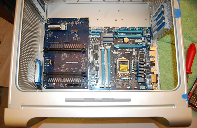
- Gigabyte Z68
- CPU
- i7-2660k
- Graphics
- GTX 560Ti
- Mac
- Classic Mac
- Mobile Phone

Hey guys,
Alright, so here we go. Yeah yeah, I know, another G5 mod.
 Well, I think I'm approaching it in a slightly different way with my own touch/flare, and I hope you guys enjoy it all the same.
Livestream:
I'm just starting this thread real quick to get it going. I'll update it soon with more information, but wanted to add this real quick because I'm on live stream cutting up my case. Thought some people may be interested. I'll try to record the sessions and put them up on the channel for people to view at the end of this if they're interested.
http://www.livestream.com/vendettathehack
The Philosophy:
I won't spend too much time here, because I'm sure you all just want to see pics and mods anyways.
My idea of a great G5 mod would be to have it as stock as possible, beautiful inside and out. Upon acquiring my case and spending countless hours sitting, staring, and analyzing it, I began to realize how realistic some of my ideas were. It actually began to feel possible, so I became more excited about the build. End goal: reuse as many original parts as possible without sacrificing functionality.
I have the build planned out, and I think I have some solid ideas, so stay tuned...
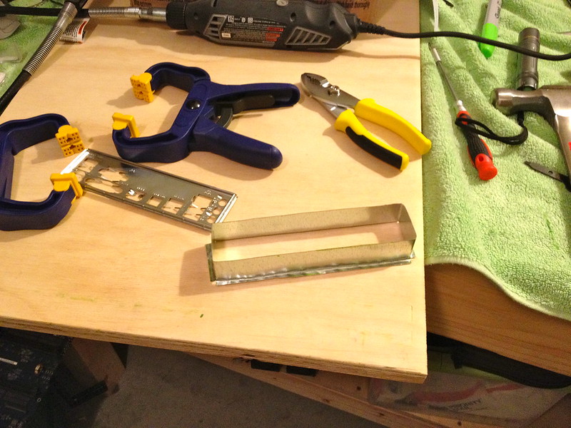
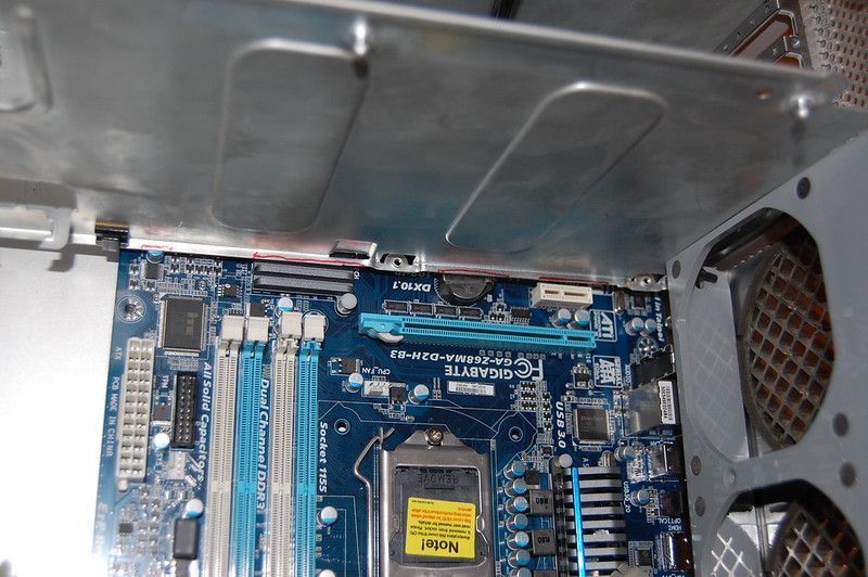
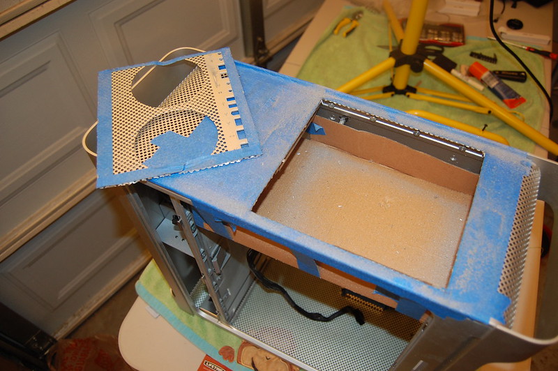
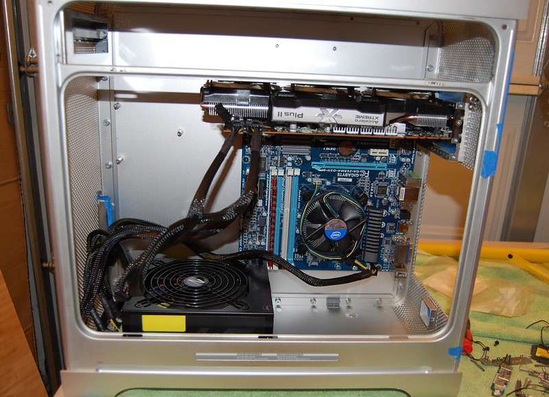
The Mod:
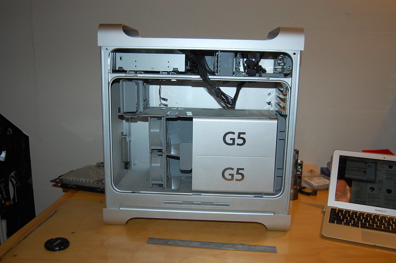
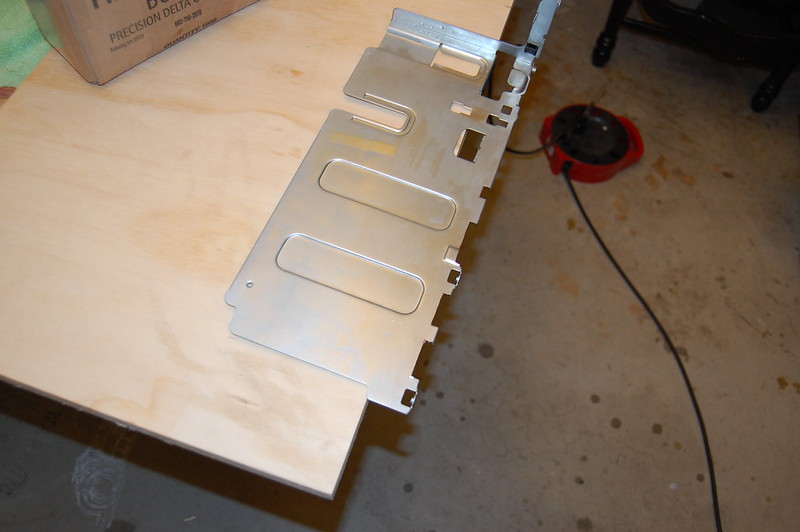
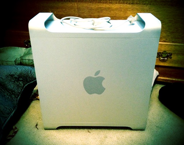
My subject.
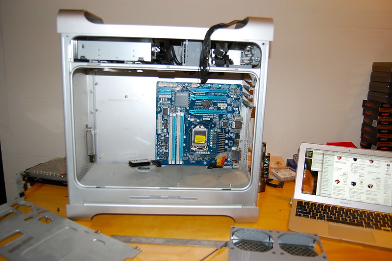
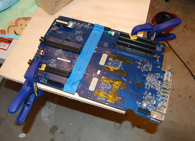
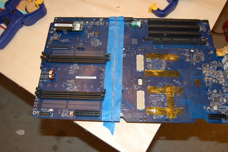
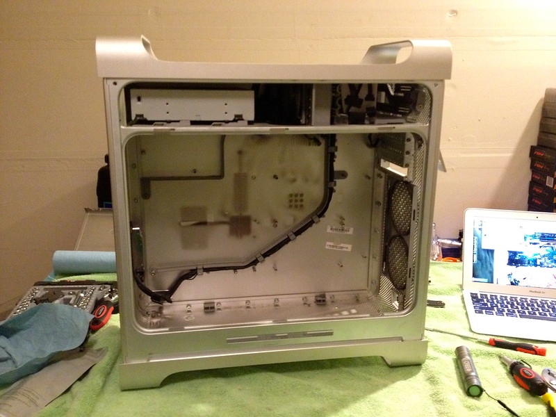
Mostly torn down.
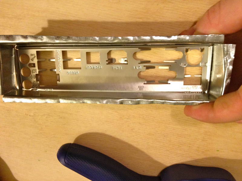
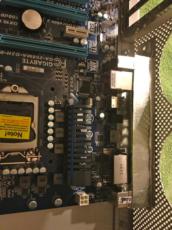
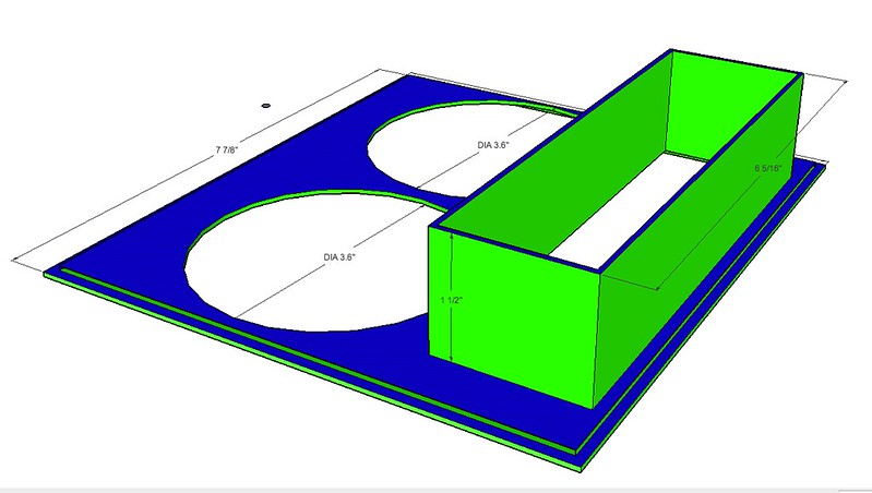
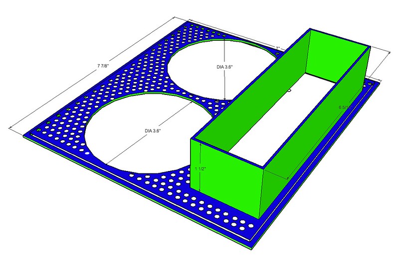
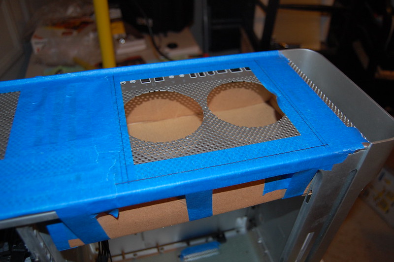
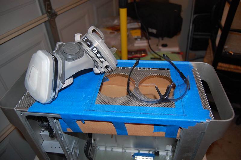
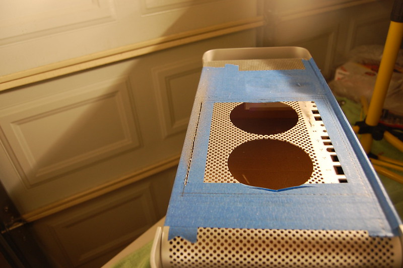
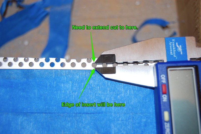
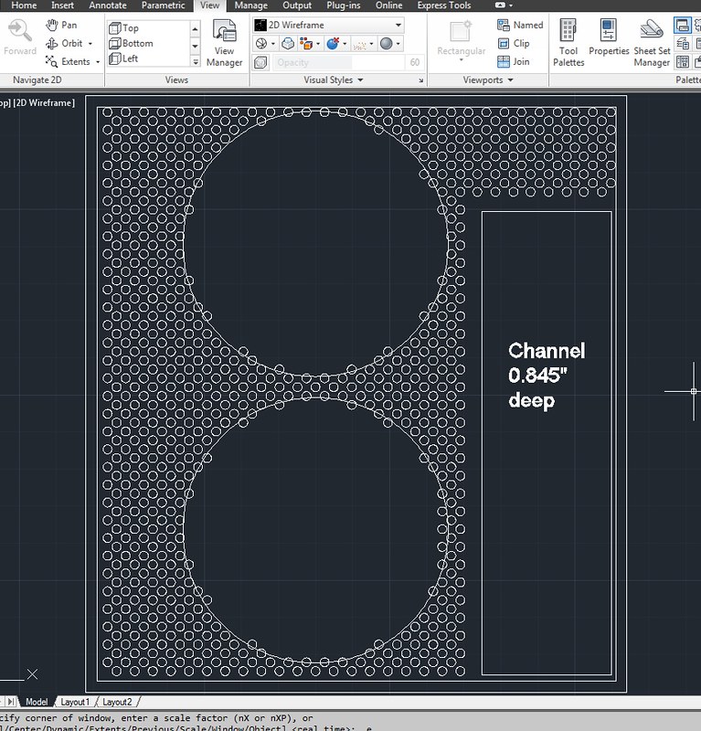
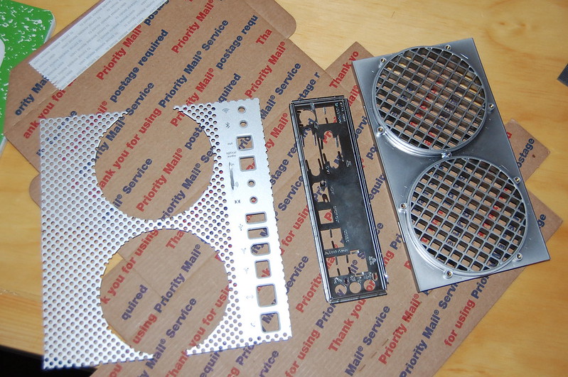
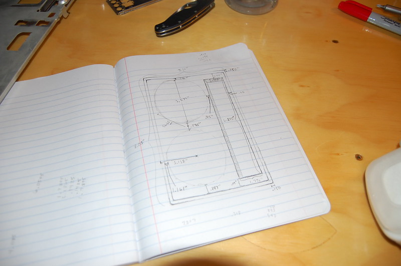
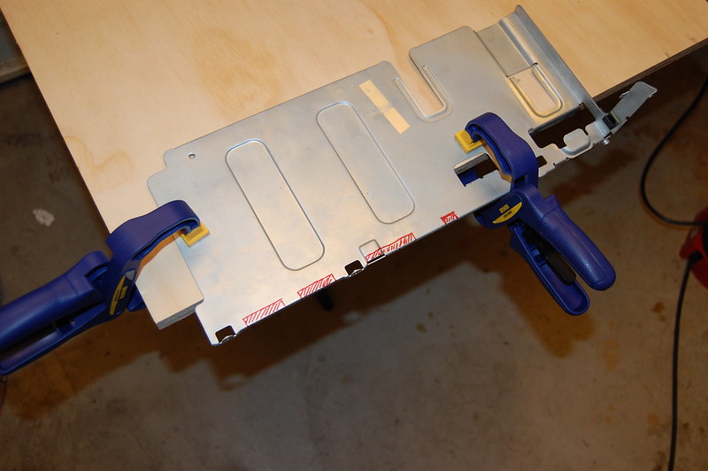
Added 4/18/2012:
Big update. Added mockups of I/O part, cut back panel, CAD of part, and more. Check it out here:
viewtopic.php?p=357317#p357317
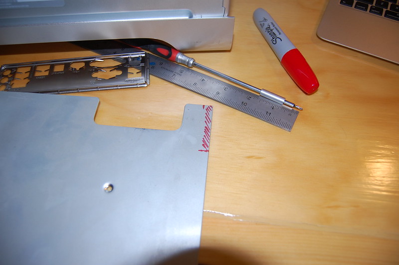
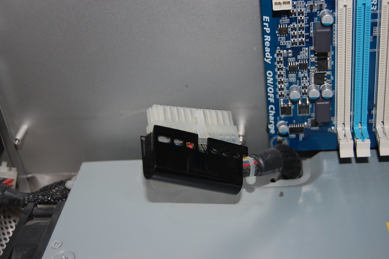
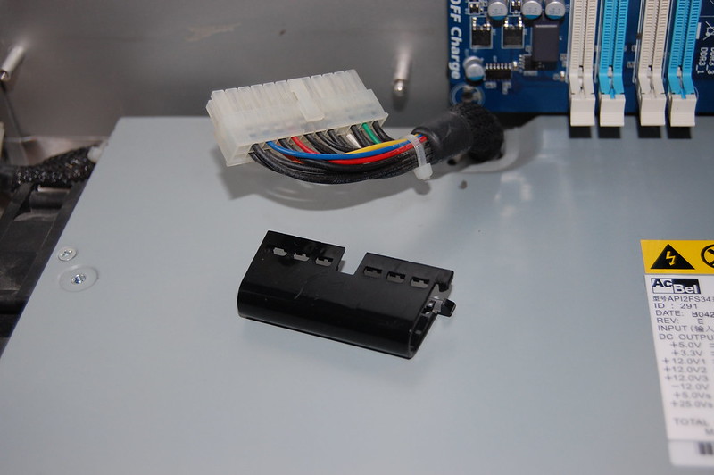
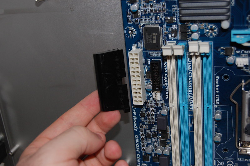
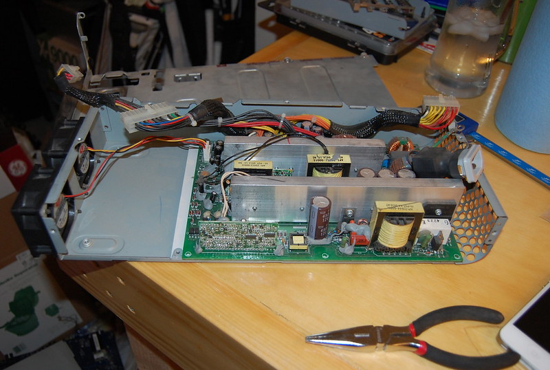
Added 4/25/2012:
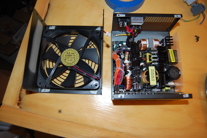
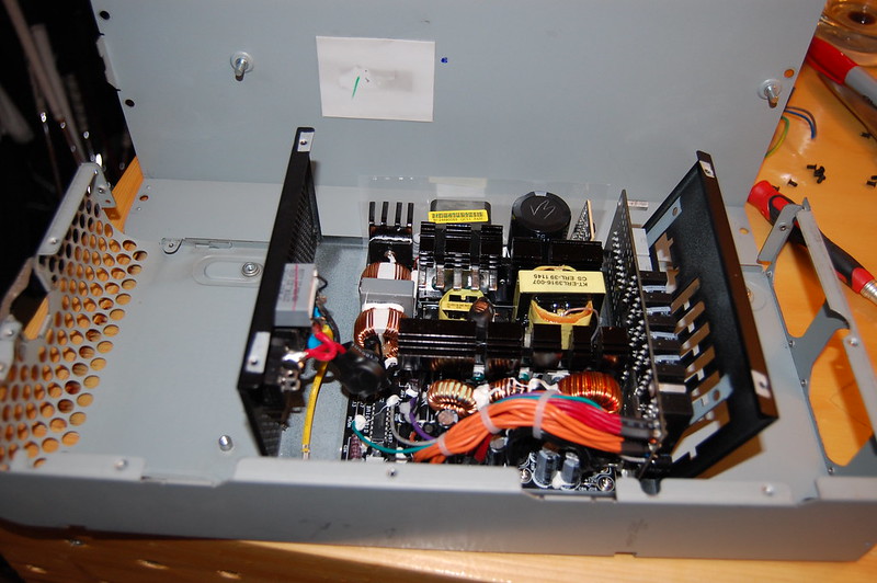
Made a few cuts and did some PSU disassembly and investigation.
viewtopic.php?p=362366#p362366
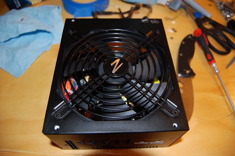
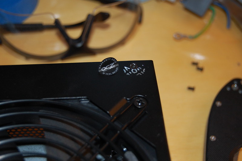
Added 4/26/2012:
A little more tinkering with the PSU, and testing out spray paint.
viewtopic.php?p=363200#p363200
Added 4/30/2012:
Cut the standoffs for the PSU, test fit some of the parts.
viewtopic.php?p=365748#p365748
Added 5/12/2012:
Making power cables custom length, as well as painted the fans.
viewtopic.php?p=374488#p374488
Added 5/13/2012:
Small update, but big progress in finishing up the PSU. Also added video of the PSU startup, fan controller, and temperature sensor.
viewtopic.php?p=375327#p375327