Contribute
Register

the_gael's G4 Quicksilver Mod

Status
Not open for further replies.
the Intel Pentium G620 that I have is also a good inexpensive CPU chip to consider
 
doctorevil30564 said:
the Intel Pentium G620 that I have is also a good inexpensive CPU chip to consider

thanks for that - I have ordered the other one just now as it was only £30. However as they are so cheap I can always replace it with something more potent if necessary. It will be used as a young kids computer with SIMS being the most intensive game they play. The rest will be web based homework, simple word processing, music, videos etc... so I guess it does not need a lot of horsepower!
 
the_gael said:
doctorevil30564 said:
the Intel Pentium G620 that I have is also a good inexpensive CPU chip to consider

thanks for that - I have ordered the other one just now as it was only £30. However as they are so cheap I can always replace it with something more potent if necessary. It will be used as a young kids computer with SIMS being the most intensive game they play. The rest will be web based homework, simple word processing, music, videos etc... so I guess it does not need a lot of horsepower!

from looking at the specs, it looks pretty similar. The G620 may have a little more cache.

I think when I bought mine from newegg the G620 was selling for 59 US dollars.

Either way good choice, it definitely sounds like it won't need a lot of power, so long as you have a good video card that is capable of playing the Sims game you should be good to go.
 
continued from 1st post

OK some updates the 2nd user GA-H61M-S2V-B3 board I bought on eBay arrived and as usual given my tech background I checked it over for any signs of overheated chips, damaged circuits etc.. I removed the CPU socket cover and instantly saw an issue - there was a bent pin. I may be able to fix it but am waiting for the seller to advise what they want to do.

I have now removed the old standoffs from the case door where the motherboard mounts. Slightly more force needed than to remove the standoffs on the G5 but still relatively straight forward.

IMG_1913.JPG

Once the standoffs were removed I placed the motherboard with a graphics card attached to give me an indication of how card slots and rear I/O ports would line up with the existing rear plate of the G4 Quicksilver. It looks fairly promising at the moment so I will mark up the rear plate for cutting out the existing built in plate for the I/O ports and make a hole where the mATX I/O ports will be accessible.

IMG_1914.JPG

I have also started preparing the front switch board for modification. I have scratched the green surface to expose the copper to make good earths as per minihack's G4 Quicksilver Switch Guide. Hopefully will get round to doing the rest of this fairly soon.

IMG_1915.JPG
IMG_1916.JPG

Although I had bought and planned to use an Antec 550 Neo modular PSU as seen I have changed my mind and have just bought an Antec BP500U as it has the power socket on the correct side for use in the G4 Quicksilver case without needing to cut the plastic (I hope).

BP500_q.jpg.png

So the next step will be cutting the G4 case to make a hole for I/O backplate - I will wait until the decision to either repair or replace the GA-H61M-S2V-B3 is finalised.
 

Attachments

  • IMG_1913.JPG
    IMG_1913.JPG
    1,016.4 KB · Views: 279
  • IMG_1914.JPG
    IMG_1914.JPG
    1.5 MB · Views: 275
  • IMG_1915.JPG
    IMG_1915.JPG
    1.5 MB · Views: 276
  • IMG_1916.JPG
    IMG_1916.JPG
    1.3 MB · Views: 273
  • BP500_q.jpg.png
    BP500_q.jpg.png
    99.4 KB · Views: 269
the saga continues...

Today I started to cut the backplate to accomodate the mATX case.

IMG_1918.jpg

the initial hole in the backpanel

IMG_1919.jpg

The motherboard was then positioned with a Graphics card attached to get the correct alignment for card slots prior to marking the metal door plate for drilling holes for standard ATX standoffs.

IMG_1920.jpg

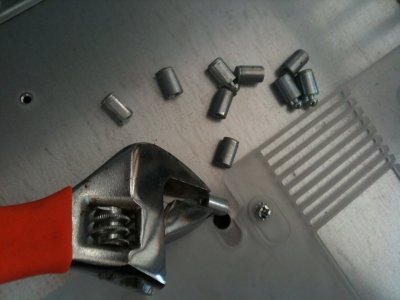
I marked the plate with a punch and drilled small holes into which to screw the ATX standoffs. They will then be locked in place with Araldite or similar glue/cement.
The standoffs were positioned and the motherboard attached to ensure positioning was correct.

IMG_1921.jpg

The motherboard was removed after I satisfied myself I could attach the motherboard to the standoffs and that it did not foul anything inside the case. I am not worried about touching the DVD drive as I will not have an internal one - will use an external DVD same as we do with a Mac Mini. This will save hassles with clearance and also give more space and hopefully contribute to keeping cool inside.

I then cemented the standoffs to lock them firmly in position. I will leave them overnight to solidify before doing anything else.

The plastic mechanism that is used for door shutting was also removed so that I could modify it to accomodate the new standoffs. That will get attached again tomorrow when the standoffs are solidified in place.

IMG_1923.jpg
IMG_1924.jpg

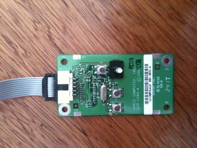
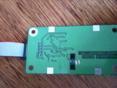
With the case moved forward as far as it will go today I turned to the front panel circuit board I had previously prepared for soldering. I soldered the appropriate connections as per minihack's guide.

IMG_1925.jpg

I then continued to follow minihack's guide to attach the ATX motherboard connectors to the original G4 ribbon cable.

IMG_1926.jpg

As I was doing the switch mod I looked at the built in wireless aerial and am considering using that with a homemade Apple Wireless Card which will get fitted when the motherboard is in place.

Enjoying myself so far - :D :headbang:
 
OK - as anyone who has looked at this thread will have noticed it has been affected by the move to the new site. I will try and completely redo the posting so that it looks right on the new site - but not right now.

Suffice it to say that the build went well and I am writing this post from the newly built G4 Quicksilver Hack :headbang:
 
Status
Not open for further replies.
Back
Top