Contribute
Register

[SUCCESS] Gigabyte Designare Z390 (Thunderbolt 3) + i7-9700K + AMD RX 580

Yes, Thunderbolt tree is still truncated. Trying a cold boot now.

EDIT: Tried a cold boot, results are the same. I wonder if something might have happened to the chip.

It's weird enough that after reflashing back to the original firmware, it still wasn't working.

Is there a way to check if the chip is fried?

There's also a very weird thing that happens after a while, when OSX is running. The system freezes completely and while that happens, it sends a weird white noise pattern type sound to the monitor's speakers. Reset button doesn't work, i have to force shut down. Worth mentioning that the default sound output isn't the monitor, it's my external USB sound card and internal audio is disabled.
Yes it's possible something may have happened to the chip. @rj510 encountered a similar issue on a similar, but not same motherboard. During flashing, he noted that flashrom reported Chip is in an Unknown State. Did you see something similar to this?

In an earlier post you stated that a friend helped to "solder" the pins. Can you describe what exactly that entailed? Were any photographs taken of that?
 
@JimSalabim,

Your screenshot, after physically replacing the Winbond chip with a new one, shows a complete Thunderbolt node for the first time. Can you please run IORegistryExplorer and scroll down to RP05, but clear the Search box so we can see the full hierarchy?

Regarding an all-zero UID, please compress and post your CLOVER folder (or OpenCore if you use that) but remove serial numbers from config.plist.

Also check if BIOS --> Thunderbolt --> GPIO3 Force Pwr is set to Enabled.
 
Yes it's possible something may have happened to the chip. @rj510 encountered a similar issue on a similar, but not same motherboard. During flashing, he noted that flashrom reported Chip is in an Unknown State. Did you see something similar to this?

In an earlier post you stated that a friend helped to "solder" the pins. Can you describe what exactly that entailed? Were any photographs taken of that?
Yes, flashrom never reported that the chip was in an unknown state, all readings and writes went fine.

I had lots of difficulties keeping the clip on the chip, so we ended up soldering little wires to all of the pins of the chip, which then were connected to the Pi.

First time it happened like this :
IMG_3701.jpg


After doing that, there was an issue with pin 4 which wasn't making contact anymore, so we desoldered the chip off the motherboard and fixed the connection.

Second time it happened like this :
IMG_3708.jpg
 
Yes, flashrom never reported that the chip was in an unknown state, all readings and writes went fine.

I had lots of difficulties keeping the clip on the chip, so we ended up soldering little wires to all of the pins of the chip, which then were connected to the Pi.

First time it happened like this : View attachment 460409


After doing that, there was an issue with pin 4 which wasn't making contact anymore, so we desoldered the chip off the motherboard and fixed the connection.

Second time it happened like this :
View attachment 460410
I have modified the Raspberry Pi instructions by recommending the low-cost clip over the Pomona 5250 because the low-cost version better encapsulates the Winbond W25Q80DV.

If you desoldered the chip off the motherboard then re-soldered the same chip back and subsequently confirmed that the chip is (a) readable, (b) has correct firmware, and (c) is not in an Unknown state, then there may be hope.
  • Have you used a magnifying glass to ensure there is no solder bridge between any of the pins?
  • Do all neighboring components on the motherboard look good? There are tiny SMD capacitors and resistors nearby. We need to ensure that there's no solder residue in any surrounding component.
  • Was the board wiped clean with 70% or higher isopropyl alcohol (IPA)?
It might be a good idea to re-flash the motherboard BIOS (not Thunderbolt firmware, but standard BIOS), then re-configure BIOS parameters once again.
 
I finally got a chance to get in a full troubleshoot.

1. Problem wasn't isolated, same issue occurred on backup disk.
2. Verified no recent changes on servers.
3. It is a managed switch, brocade ICX6610. Settings are as they should be.

That being said, I did discover/uncover the underlying issue. There seems to be some form of incompatibility with selecting jumbo frames is system preferences/network. This has never posed an issue prior to now. I was always able to select MTU 9000, and operate accordingly. With 9000 MTU, various LAN addresses are inaccessible via all browsers, connection issues over SMB and AFP (finder will free while connecting, freeze while accessing/transferring, generally slow SMB and AFP transfers, mounted ISCSI volumes dropping, mounted SMB shares disconnecting seemingly at random.
When you say you were "always able to select MTU 9000", are you referring to Network Settings on the Hackintosh? The paragraph below states that MTU will not "stick" whether selected from the pop-up menu or entered as a manual value.
As seen in the pictures, 9000 MTU will not autoselect, so I have to select the pictured settings to see Jumbo frames as an option. With the pictured settings, 1500 MTU selected, expected operation. Jumbo frames selected, the issues occur. When I select Custom, enter 9000 MTU changes will not save. When I select Custom, enter (the max) 10222 MTU changes will not save. (note on Custom: I am able to hit save, then apply in the network settings, however the changes applied do not stick. When I return to configuration, the MTU is reset to 1500.
Are the screenshots for (a) WiFi or (b) Wired Ethernet? Or the same inability to set jumbo frames applies to both?
With MTU set to 1500, it at least appears to be workable. I just discovered this issue, so have not been able to fully test. But I can access all LAN locations, SMB shares seem to be stable. SMB shares are underperforming, in limited trial, but have historically with 1500 MTU selected. So, I'd like to figure a way past this issue, and get back to optimal network settings, as some of my use-case is high-performance-dependent.
It's fairly common to use jumbo frames for communication with NAS so I agree it's desirable to find a solution.
I will also note when the NIC's are plugged in, with no changes, literally unplug from this workstation, pluginto macbook pro, plugged into rackmount mac pro, no issues whatsoever. So, seems contained to customac only. I've tried two different Chelsio T4 NIC's, Two different (same model) T5 NIC's, and one T6 NIC, with the same results. NIC firmware is the most recent, Catalina approved. Most recent catalina kext is installed.

I'm seeing if it may be a chelsio issue, i've reached out to their support. But, curious if any further insight can be given. I wish i had access to another mac compatible 10GbE+ NIC, but can't get my hands on any other brand, due to current availability.
So this issue happens with a Chelsio T4 PCIe card? Does it have an Aquantia or Intel or some other controller?
 
I installed the new Lilu/WhateverGreen/AppleALC/VirtualSMC that were released yesterday. I was unable to fully boot until I reverted the VirtualSMC to the previous version.

The message in verbose was busy timeout for AppleACPICPU

Any clue as to what I need to do to keep up with VirtualSMC?

Running 10.14.6

Thankfully it had booted far enough to SSH in, but black screen locally.

Thanks!

Same problem here with the new VirtualSMC. Does anyone know why?
 
Same problem here with the new VirtualSMC. Does anyone know why?

I got it working.
  • Updated to latest OCQuirks.efi/OpenRuntime.efi
  • Removed VirtualSmc.efi/FwRuntimeServices.efi
  • Updated VirtualSMC.kext/SMC*.kext
 
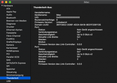
Your screenshot, after physically replacing the Winbond chip with a new one, shows a complete Thunderbolt node for the first time. Can you please run IORegistryExplorer and scroll down to RP05, but clear the Search box so we can see the full hierarchy?

Regarding an all-zero UID, please compress and post your CLOVER folder (or OpenCore if you use that) but remove serial numbers from config.plist.

Also check if BIOS --> Thunderbolt --> GPIO3 Force Pwr is set to Enabled.
Clover folder attached (but it makes no difference whether I use OpenCore or Clover).
GPIO3 Force Pwr is set to Enabled, yes.

Interestingly this time I could even flash the patched firmware to the chip once again in Windows with the Gigabyte Thunderbolt Firmware Update Tool. With the old (and probably defective or let’s say destroyed) chip this was not possible, because the chip was not detected at all.
But anyway, this didn’t help either. And Windows doesn’t find my MOTU 8A Thunderbolt interface either.

I have already tried it with different custom numbers for DROM, but all no difference.

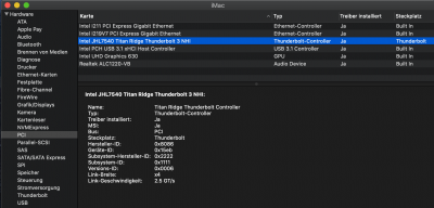
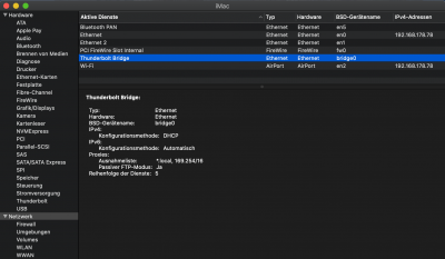
Here are my screenshots:
Bildschirmfoto 2020-04-08 um 00.25.01.png
Bildschirmfoto 2020-04-08 um 00.22.54.png
Bildschirmfoto 2020-04-08 um 00.22.35.png
Bildschirmfoto 2020-04-08 um 00.23.59.png
In Hackintool the USB-C part of the Thunderbolt ports is also not detected anymore.
 

Attachments

  • EFI-JimSalabim.zip
    5 MB · Views: 85
I have modified the Raspberry Pi instructions by recommending the low-cost clip over the Pomona 5250 because the low-cost version better encapsulates the Winbond W25Q80DV.

If you desoldered the chip off the motherboard then re-soldered the same chip back and subsequently confirmed that the chip is (a) readable, (b) has correct firmware, and (c) is not in an Unknown state, then there may be hope.
  • Have you used a magnifying glass to ensure there is no solder bridge between any of the pins?
  • Do all neighboring components on the motherboard look good? There are tiny SMD capacitors and resistors nearby. We need to ensure that there's no solder residue in any surrounding component.
  • Was the board wiped clean with 70% or higher isopropyl alcohol (IPA)?
It might be a good idea to re-flash the motherboard BIOS (not Thunderbolt firmware, but standard BIOS), then re-configure BIOS parameters once again.

Well I have the low cost clip and I couldn't fit it once. Must be a different one maybe.

We have not used a magnifying glass but I believe my friend did a pretty good job and was clean about it.​

Yes, he used IPA to clean the motherboard after each solder. I'm actually going to get a magnifying glass and take a closer look.​

Neighboring components look alright, maybe you can give us a second opinion.​
After your message, I went ahead and took a closer look.

As you can see from the photos, the solder of pins 7-8 looks a little weird from one angle, so I checked if they're shorted. They were not.

After comparing to some photos I took before soldering, I realized that there is one capacitor/resistor missing right above pin 7-8 of the chip.

Do you mind taking a photo of your chip and the surrounding area so we can do a comparison?
Maybe also measure what kind of resistor/capacitor is that in case it's replaceable.

Here's the "before" picture:

IMG_3694.jpg


Here's the "after"

IMG_3718.jpg

IMG_3715.jpg


After that, I checked pin 7 and the right pin of the missing component and they're connected. Then I measured the left pin's voltage while powered and it's 3,3v.

Since pin 7 was essentially disconnected, the chip wouldn't work without it. So I went ahead and connected those two pins together with some flux, then voila, thunderbolt is working.

Screenshot 2020-04-08 at 02.02.31.png


I was blown away by how everything worked just like that. My TB1 hard drive is suddenly recognized. Sleep/wake worked like a charm. WOW!

Tried a warm boot to Windows and it recognized the already connected hard drive there as well.
Under windows, thunderbolt software still doesn't show the ports and hot plug did not work.

Anyway, back to OSX, ioreg is fully populated now.
I hope the UID is properly assigned and there won't be any issues with that.

Screenshot 2020-04-08 at 01.56.55.png


@CaseySJ thank you so much for sticking it out with us, really appreciate your contribution to this community. Big shout out to my friend that soldered this for me, I didn't trust myself enough to solder something like that.
 
Last edited:
@bugsyraz This could be exactly my problem, too! The small component at pin 7 is missing here as well! I think it was ripped off the board while trying to get the SOIC-8 clip in the right position.
I will bridge the two pins now (as long as we don’t know which value the capacitor or resistor is) and tell you how this works out.
 
Last edited:
Back
Top