Contribute
Register

[SUCCESS] Gigabyte Designare Z390 (Thunderbolt 3) + i7-9700K + AMD RX 580

Hi!
@NorthAmTransAm
Does the TB add-in card work in Windows after flash?
Fantastic work everyone!!!
@Oggy,
on my Z390 Designare that include patched firmware, it work well on Windows but I have to boot to macOS with thunderbolt device connected then reboot to Windows (without shutdown). I have tried with eGPU. Unfortunately, I don't have Hotplug feature.
 
I have found that with my motherboard and AIC both the Alpine ridge and the Titian ridge both work better if I use 3-5 pin jumper to force power. SSDT required for Hotplug.
@scottkendall
Of course, but Losinka's motherboard include an onboard thunderbolt controller.
 
No more test for now, Really strange that you have nothing : Have you enabled GPIO3FrPwr on BIOS ?
If that is the case, for your Alpine Ridge model, SSDT only would be a better solution :) but not the simplified model related to patched Firmware, another that could reconfigure registers.
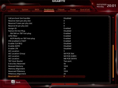
My Thunderbolt BIOS:
TB-Bios-1.jpgTB-Bios-2.jpg
 
@Oggy,
on my Z390 Designare that include patched firmware, it work well on Windows but I have to boot to macOS with thunderbolt device connected then reboot to Windows (without shutdown). I have tried with eGPU. Unfortunately, I don't have Hotplug feature.

Though a one byte difference in the firmware mine still can't be cold booted into windows as well. Like the rest of us I can go from macOS to Windows and have thunderbolt (my my my how the turn tables).

I'm booting Windows through OpenCore with an Osi statement on each ACPI patch as well. I'm sure we could come up with an SSDT to go from OC/Clover to Windows. By we I mean...not me :)

Update: I removed all Osi statements and Windows still boots fine. That's a little off topic yet news to me. I suppose not all patches hurt Windows or OC 056 does something new.

One note during testing. If you cold boot into Windows (from bios or Clover/OC) and then warm boot into macOS then you will lose Thunderbolt and need to shut down and unplug. In other words, don't freak out. You didn't break anything. As far as I can tell you can go from Mac to Windows and back again (a Hobbits tale) and be just fine.
 
Last edited:
Hello @Gottgenk,

I've briefly looked at the egpu.io link, but since I'm most familiar with the external-flasher method, let's see if we can look into that first:
  • Can you describe or photograph the circuit you used?
  • Are you using a 47uF or 100uF polarized capacitor and connecting the long leg to + and the short leg to -?
  • Are you using a 2K Ohm resistor before Pin 3 of the SOIC clip? I've tried 1K and 10K Ohm resistors, but neither of those works. A 2.5K or 5K Ohm resistor may work, but let's stay with 2K Ohm.
  • Have you physically pulled the plug from the computer's power supply?
  • Are you securely attaching the SOIC clip to the Designare chip before powering on the Raspberry Pi?
  • When you power on the Raspberry Pi with the clip connected to Designare, what is the color of the array of LEDs on the back of the motherboard?
  • Are the LEDs stable or blinking?
  • Have you tried momentarily disconnecting pin 3 with everything else connected, and re-inserting pin 3?

@CaseySJ

- I am using the breadboard, 47uF capacitor and resistors from my Arduino Kit. The long leg of the capacitor is connected to the + and the short to the -. I did not have a 2K Ohm resistor so I serial connected two 1K Ohm resistors to get the 2K Ohm.
- The plug from the power supply was physically unplugged. I unplugged other cables from the motherboard as you advised in another reply in this tread.
- The SOIC clip is well attached, I then booted the RPi, the leds turn on and are red. They do not blink.
- I tried disconnecting pin 3 for a couple of seconds as you described, and then re-connect it.

Up to now I have not managed to read the chip even once.

Do you think a 100uF capacitor could work? I would have to order some to try.
 

Attachments

  • IMG_2253.JPG
    IMG_2253.JPG
    2.9 MB · Views: 106
@CaseySJ

- I am using the breadboard, 47uF capacitor and resistors from my Arduino Kit. The long leg of the capacitor is connected to the + and the short to the -. I did not have a 2K Ohm resistor so I serial connected two 1K Ohm resistors to get the 2K Ohm.
- The plug from the power supply was physically unplugged. I unplugged other cables from the motherboard as you advised in another reply in this tread.
- The SOIC clip is well attached, I then booted the RPi, the leds turn on and are red. They do not blink.
- I tried disconnecting pin 3 for a couple of seconds as you described, and then re-connect it.

Up to now I have not managed to read the chip even once.

Do you think a 100uF capacitor could work? I would have to order some to try.
EE101: connect 2 47uF caps in parallel. twist the negative leads together, twist the positive leads together, solder the twists if you can, then bend back one of the negs and pos so you can plug the other neg and pos into the breadboard.

from the Google machine:

When capacitors are connected in parallel, the total capacitance is the sum of the individual capacitors’ capacitances. If two or more capacitors are connected in parallel, the overall effect is that of a single equivalent capacitor having the sum total of the plate areas of the individual capacitors. As we’ve just seen, an increase in plate area, with all other factors unchanged, results in increased capacitance.

capacitors connected in parallel

capacitors and resistors behave in opposite manners when in series or parallel. series resistors are additive, parallel capacitors are additive.
 
Last edited:
@CaseySJ

- I am using the breadboard, 47uF capacitor and resistors from my Arduino Kit. The long leg of the capacitor is connected to the + and the short to the -. I did not have a 2K Ohm resistor so I serial connected two 1K Ohm resistors to get the 2K Ohm.
- The plug from the power supply was physically unplugged. I unplugged other cables from the motherboard as you advised in another reply in this tread.
- The SOIC clip is well attached, I then booted the RPi, the leds turn on and are red. They do not blink.
- I tried disconnecting pin 3 for a couple of seconds as you described, and then re-connect it.

Up to now I have not managed to read the chip even once.

Do you think a 100uF capacitor could work? I would have to order some to try.
  • The circuit looks correct.
  • On the Designare I was only able to read the chip with 47uF capacitor.
  • I tried this procedure on the Designare again this morning and had to unclip and re-clip the Winbond chip. We can do this with Raspberry Pi still turned on.
  • The SOIC clip should "swallow" the Winbond chip. Try gently unclipping and re-clipping the Winbond.
Also try changing spispeed to 1024 and 4096.
 
I found with my clip that I had to carefully eyeball both sides of the clip/chip to make sure the clip's pins are perfectly aligned with the leads on the Winbond chip. With the "acceptable quality clip" that I bought, there was a little sloppiness at the hinge. So, when one side of the clip was aligned with the leads on the chip, the other side of the clip wasn't necessarily aligned. I found this to be the case on the GC-alpine and the NUC. From what I have read here the Designare is even trickier to get the clip perfectly aligned.
 
Last edited:
Back
Top