- Joined
- Sep 30, 2011
- Messages
- 56
- Motherboard
- i7 HackPro
- CPU
- Core i7
- Graphics
- Nvidia
- Mac
- Classic Mac
- Mobile Phone
Has anyone ever accomplished this? I found several search results where people mention trying (often ending in giving up) but no clear success stories.
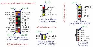
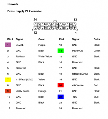
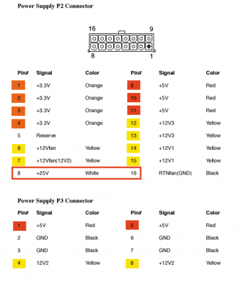
As I undertake it the stock G5 PSU is a 1000w model, at least so says the guy whom I'm buying the case from. For my build I'm thinking a 400-500w replacement would do, but honestly, reusing the Apple model seems like it would not only save me a few dollars, but provide a ton of extra wattage for future expansion possibilities.
I'm very handy with a voltmeter, soldering iron, etc, and aren't afraid to get down and dirty...but I guess the big question is, does the stock G5 PSU provide the proper voltages required for a hackintosh build using all the regular hardware?
Thanks all.