- Joined
- Sep 1, 2011
- Messages
- 143
- Motherboard
- Gigabyte Z68X-UD3H-B3
- CPU
- i5-2500
- Graphics
- HD 6870
- Mac
- Mobile Phone
I'm working on my PSU and I've gotten a bit stuck. 
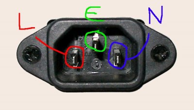
I need a diagram for the C13/C14 IEC receptacle.
I know the bottom one is "earth ground", but I'm kind of debating which wires go where for the top two. (I'm retarded and didn't take a picture or remember which way they went when I de-solderer them...)
I noticed there was a difference between the wiring of the G5 PSU receptacle and an ATX PSU receptacle, if only slightly.
The ATX PSU had a bridge between the two top points.
My PSU only has 2 wires coming from the board to the IEC. (A red and a black; and I'm assuming that would be + and GND) and I planned on removing the ON/OFF switch as I don't really need it.
My assumption is that the left is + and the right is GND, but I didn't want to be wrong..