- Joined
- Mar 4, 2011
- Messages
- 32
- Motherboard
- Gigabyte P55M-UD2
- CPU
- i7
- Graphics
- GT 630
- Mac
- Mobile Phone
Preface:
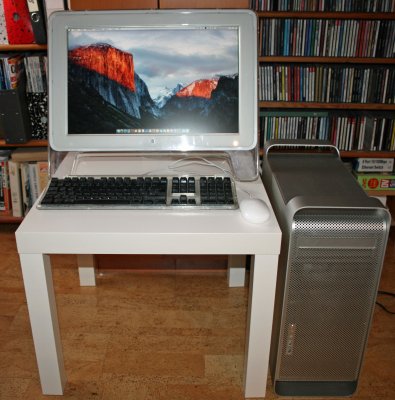
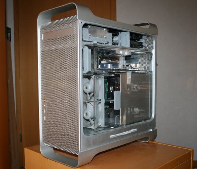
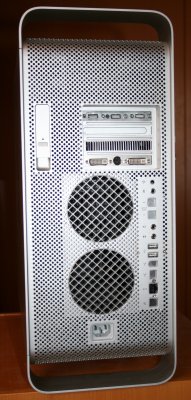
Purpose of the modification was to give an existing El Capitan PC installation an "appropriate" housing, a.k. an original G5 case. This modification has been done retaining the EXTERNAL look (front and back) as well as keeping the internal structure as close as possible to it's original state.
Based on previous experiences, but most importantly based on the great ideas in this forum this modification succeeded with a great looking system.
Basic system specs:
Essentials:
And here the result:
The Story:
My son came by bringing in a G5 and asked me, if I could fix it.
Turned out, that the machine was overall in very good, almost mint condition, but would not start. The fans were humming at full throttle, but no boot and the pilot light would only flash when pushing the button. Going through the regular debug steps, validating the PSU, RAM and graphics I took the CPUs out and discovered the obvious problem: Leakage of cooler had lead to severe corrosion on the processor modules. Cleaning did not help it, so I declared the box "non recoverable" from an economic perspective.
But turning it into a hack, given the shiny state of the case was a real option, especially because we had a fully operational Hackintosh sitting in a dull PC case.
Getting to work on the G5, step 1 the PSU:
So I removed the motherboard, removed the power supply and all the other collateral and started the work.
The original PSU was healthy (the corrosion had not continued into the power supply case!), so I figured I'd be able to rewire the harness to fit an ATX layout. Based on pin out information I found on the web I discovered the color code of our model was different, but the pin positions were matching exactly.
Here is what I did:
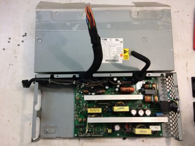
I chopped off the original power supply connectors and patched the cables to a set of existing ATX cable (from a dead ATX supply) and shrink tubed every single solder joint.
I trimmed the cable in length to fit exactly to the targeted positions of the new motherboard and reused the existing outlet holes of the PSU case.
The original P3 connector (serving the drive bay) was left entirely intact (matches the needs for the hard drives), P2 carries all the 3.3V leads, which needed to the pulled over (internally to the PSU) to show at the 24 pin ATX connector. The MAC supply has fewer 5V leads, so I had to splice 2 leads for the ATX end.
The MAC 12V supply is split into 3 rails, I routed the 12V 1 rail over the ATX 24 pin header and used 12V3 to feed the auxilliary P4 ATX header. The original 12V fan supply, fan return, fan tacho, 25V line as well as 12V audio/audio RTN are NOT in use for ATX, so I taped them up and kept them internal to the PSU housing.
The MAC PSU also has a 5V sense line, so I routed it to one of the ATX 5V leads colse to the ATX connector end.
The MAC PSU has NO -5V, which to todays ATX spec is no longer required and it also does NOT provide a power OK signal. Apparently my motherboard does not really need it, so this line was left non connected. There are motherboards out there NEEDING it, then you may have to fake it by pulling it up to the 5V rail.
And guess what: The supply fired up my motherboard with no glitches!
I do want to make note, that the original MAC supply has roughly 600W with different max current per rail distribution than an ATX supply, so you may have troubles adding a juicy graphics card. In my case, I am using a simple GPU with no auxilliary supply rails, so I am good.
I do recommend to replace the PSU fans with some silent types, the original fans do make some good noise to start with!
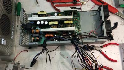
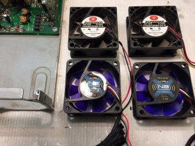
So I replaced the fans with NB types, 60mm size. Note the the fan post type connectors do not follow standard layout, so repositioning of the cables in the socket required!

I have attached my wiring table for the MAC to ATX conversion, in case anybody wants to save to time to look up the details from www.
Mother board and backplate:
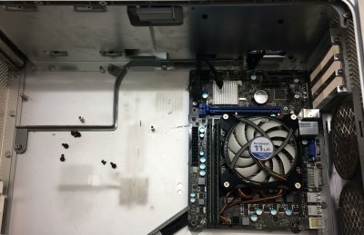
I repurposed an existing MSI H61M uATX board and this time I wanted to leave the backside of the G5 box untouched. Here the trial fit of the motherboard:
I had to rewire the REQUIRED backpanel connections of the mobo. A short inventory of my case said the following:
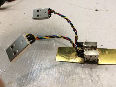
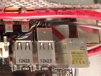
Created a 2 USB “mini extensions” to rewire 2 backplane ports to the MAC backside panel. Two flanges soldered to the sockets hold the sockets to the backpanel of the Mac.
Created 3 short 3.5mm extensions with panel mounting sockets. The sockets mount in the original position for headphone and line, the mic socket fills the bluetooth antenna hole.
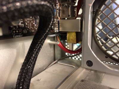
For LAN I salvaged a patch cable and attached a LAN socket to the end. This socket is mounted to the original LAN port position of the G5 case with a little brass bracket (fits right next to the PS2 connector block of the motherboard) , fixed to the housing with 2 torx screws (barely visible)
All this is very tight, but the mobo fits and lines up perfectly to the original extension slot openings. I broke off the standoffs from the MAC case, fixed them to the motherboard and glued them back in place with 2k epoxy.
USB adapter slot assy:

USB to MAC rear panel extension:

LAN “detour”:
Audio I/O:
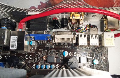
(here the motherboard is not repositioned in correct place, but you get an idea of how tight this rewiring gets in the about 15mm clearance between motherboard edge and backpanel of the case!
And how it looks:

Front panel:
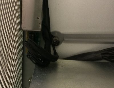
There are plenty of illustrations available how to wire up the original panel, so I save the details here, but I want to highlight, that it is MANDATORY to attach the firewire ground/shield to ground even if you don't need the firewire socket (like in my case), because the power button is referenced to FW ground in case of the MAC, so the power button will not work with no ground to FW attached!
USB, button, LED and audio wiring is straight forward, I repurposed the little pigtail cable of the MAC, cut it into pieces and extended all signals to reach the motherboard connectors using a shielded 9 wire data cable and spliced the ATX connectors to it.

Getting Front Panel Audio AUTOSENSING to work!
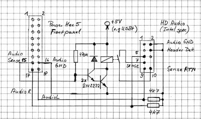
As many experts and users have discovered: PowerMAC G5 front panel jack sensing method is not compatible with “Intel HD Audio” front panel standard, so I created a little extra circuitry to help that: The G5 sense line ( a normally closed connection to the audio right channel) drives a transistor switch, which activates a tiny Reed relay. The contacts of the relay short the Intel HD audio sense send and return lines for the audio out, and voala: Front panel head phone detection works flawlessly (likewise under Win7).
Here the circuitry I have used:
Upper drive compartment:
I removed the radial fan, removed the SATA cables (they are too short to reach the mobo anyway), removed the optical drive with it's parallel IDE cable, chopped off the 4 pin molex header (was for the optical drive) and spliced 2 sata power headers. I put in 4 SATA cables, which find their way through the empty fan frame right to the edge of the mother board.
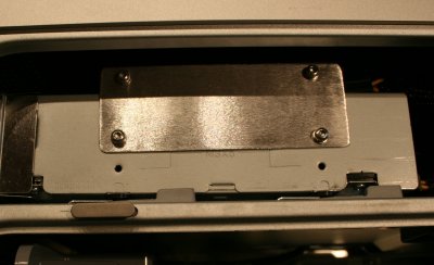
A new SATA optical drive mounts back in place, the SSD is sitting on top pf the DVD drive and is held in place with a little sheet metal, the original hard disk bay holds two standard SATA HDDs, so total of 4 drives matching the 4 SATA outputs of the mobo.
Mechanics:
The original devider is mounted to the MAC PCB, well, this does not work with the ATX board, so a little cutting is required to make room for the mother board components, yet to the front side of the MAC everthing can stay untouched. Remains the question how to fix the divider plate at the "rear end" of the box. There is an ATX mounting point right under the GPU slot at the edge of the PCB, I figured a little L shaped piece of metall could act as a leg for the divider, fixed with a mounting screw of the motherboard. On a similar note I added a piece of epoxy material in the front portion of the case to resemble the mount points for the divider frame equivalent to what the original motherboard does.
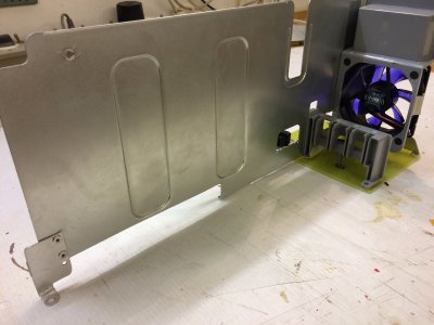
That way:
The divider sits in place like in the original G5, the fan/speaker assy sits in the right spot and front fan assy for the processor plus the processor cover plate sit where they belong.
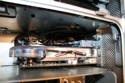
The back side fan assy collides a bit with the audio connector "tower", so I had to cut off a little from the fan frame.
At this point I have removed the rear fans, left the others in place, however they are not wired up. From past experience there is no extra "help" via chassis fans required. The case is different for the GPU section, the fan helps to keep the graphics cool, so I have replaced the original fan with a silent 80mm NB type and wired it up to the motherboard.
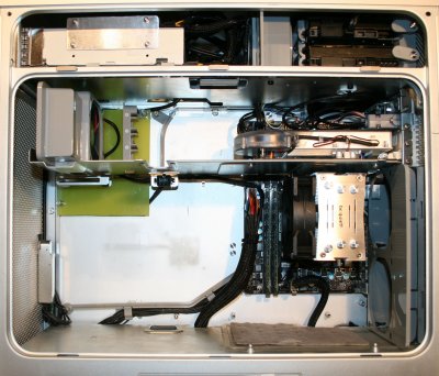
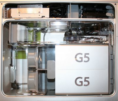
All in all:
Compared to the previous two G5 modifications I did this went a lot easier from a mechanical perspective, yet a whole lot more work in terms of soldering custom cabling, a.k. the PSU thing, the USB pigtails and so forth, but I am pleased with the turn out, having done my first G5 modification with an untouched backside.
The system is absolutely dead quiet besides noise of the hard disks .It's running smoothly and reliably, all intended and installed functionality is in place.
The main use of the system will be audio processing in a home studio environment, that´s why I am sensitive to background noise.
Agains THANKS to this great forum with all the detailed tips and tricks!
Attachments:
PSU to ATX wiring table (pdf)
Front Panel Wiring Table (pdf)
Purpose of the modification was to give an existing El Capitan PC installation an "appropriate" housing, a.k. an original G5 case. This modification has been done retaining the EXTERNAL look (front and back) as well as keeping the internal structure as close as possible to it's original state.
Based on previous experiences, but most importantly based on the great ideas in this forum this modification succeeded with a great looking system.
Basic system specs:
- MSI H61M P31 motherboard (socket 1155)
- Intel Pentium i5 3750 (Ivy Bridge)
- beQuiet Slim Rock
- 4G DDR RAM (2 DIMMs)
- AMD Radeon HD 4670 (works OOB!)
- LG DVD drive (SATA)
- 120G Kingston SSD (El Capitan)
- 1TB WD green SATA HDD (Data)
- 160G Seagate SATA HDD (Win 7)
- MAC G5 PSU (rewired to ATX), new NB fans
- Original Apple Cinema Display 20 inches (with DYI ADC to DVI adapter)
- Dual boot with Clover, MAC OS El Capitan and Win 7
Essentials:
- No backside cut out!
- Original mechanical layout with fan holders and covers!
- Original G5 PSU rewired for ATX use!
- Working original front panel, including headphone sensing (FW not used)!
- Super silent!
And here the result:


The Story:
My son came by bringing in a G5 and asked me, if I could fix it.
Turned out, that the machine was overall in very good, almost mint condition, but would not start. The fans were humming at full throttle, but no boot and the pilot light would only flash when pushing the button. Going through the regular debug steps, validating the PSU, RAM and graphics I took the CPUs out and discovered the obvious problem: Leakage of cooler had lead to severe corrosion on the processor modules. Cleaning did not help it, so I declared the box "non recoverable" from an economic perspective.
But turning it into a hack, given the shiny state of the case was a real option, especially because we had a fully operational Hackintosh sitting in a dull PC case.
Getting to work on the G5, step 1 the PSU:
So I removed the motherboard, removed the power supply and all the other collateral and started the work.
The original PSU was healthy (the corrosion had not continued into the power supply case!), so I figured I'd be able to rewire the harness to fit an ATX layout. Based on pin out information I found on the web I discovered the color code of our model was different, but the pin positions were matching exactly.
Here is what I did:
I chopped off the original power supply connectors and patched the cables to a set of existing ATX cable (from a dead ATX supply) and shrink tubed every single solder joint.
I trimmed the cable in length to fit exactly to the targeted positions of the new motherboard and reused the existing outlet holes of the PSU case.
The original P3 connector (serving the drive bay) was left entirely intact (matches the needs for the hard drives), P2 carries all the 3.3V leads, which needed to the pulled over (internally to the PSU) to show at the 24 pin ATX connector. The MAC supply has fewer 5V leads, so I had to splice 2 leads for the ATX end.
The MAC 12V supply is split into 3 rails, I routed the 12V 1 rail over the ATX 24 pin header and used 12V3 to feed the auxilliary P4 ATX header. The original 12V fan supply, fan return, fan tacho, 25V line as well as 12V audio/audio RTN are NOT in use for ATX, so I taped them up and kept them internal to the PSU housing.
The MAC PSU also has a 5V sense line, so I routed it to one of the ATX 5V leads colse to the ATX connector end.
The MAC PSU has NO -5V, which to todays ATX spec is no longer required and it also does NOT provide a power OK signal. Apparently my motherboard does not really need it, so this line was left non connected. There are motherboards out there NEEDING it, then you may have to fake it by pulling it up to the 5V rail.
And guess what: The supply fired up my motherboard with no glitches!
I do want to make note, that the original MAC supply has roughly 600W with different max current per rail distribution than an ATX supply, so you may have troubles adding a juicy graphics card. In my case, I am using a simple GPU with no auxilliary supply rails, so I am good.
I do recommend to replace the PSU fans with some silent types, the original fans do make some good noise to start with!

So I replaced the fans with NB types, 60mm size. Note the the fan post type connectors do not follow standard layout, so repositioning of the cables in the socket required!


I have attached my wiring table for the MAC to ATX conversion, in case anybody wants to save to time to look up the details from www.
Mother board and backplate:
I repurposed an existing MSI H61M uATX board and this time I wanted to leave the backside of the G5 box untouched. Here the trial fit of the motherboard:

I had to rewire the REQUIRED backpanel connections of the mobo. A short inventory of my case said the following:
- Need wired LAN connection!
- Need min 4 USBs, prefer 6, the mobo features 4 USBs available on pin headers!
- No need for integrated video out, cause I am using a separate graphics card anyway!
- Need / want the audio I/O.
Created a 2 USB “mini extensions” to rewire 2 backplane ports to the MAC backside panel. Two flanges soldered to the sockets hold the sockets to the backpanel of the Mac.
Created 3 short 3.5mm extensions with panel mounting sockets. The sockets mount in the original position for headphone and line, the mic socket fills the bluetooth antenna hole.
For LAN I salvaged a patch cable and attached a LAN socket to the end. This socket is mounted to the original LAN port position of the G5 case with a little brass bracket (fits right next to the PS2 connector block of the motherboard) , fixed to the housing with 2 torx screws (barely visible)
All this is very tight, but the mobo fits and lines up perfectly to the original extension slot openings. I broke off the standoffs from the MAC case, fixed them to the motherboard and glued them back in place with 2k epoxy.
USB adapter slot assy:

USB to MAC rear panel extension:


LAN “detour”:

Audio I/O:

(here the motherboard is not repositioned in correct place, but you get an idea of how tight this rewiring gets in the about 15mm clearance between motherboard edge and backpanel of the case!
And how it looks:

Front panel:
There are plenty of illustrations available how to wire up the original panel, so I save the details here, but I want to highlight, that it is MANDATORY to attach the firewire ground/shield to ground even if you don't need the firewire socket (like in my case), because the power button is referenced to FW ground in case of the MAC, so the power button will not work with no ground to FW attached!
USB, button, LED and audio wiring is straight forward, I repurposed the little pigtail cable of the MAC, cut it into pieces and extended all signals to reach the motherboard connectors using a shielded 9 wire data cable and spliced the ATX connectors to it.


Getting Front Panel Audio AUTOSENSING to work!
As many experts and users have discovered: PowerMAC G5 front panel jack sensing method is not compatible with “Intel HD Audio” front panel standard, so I created a little extra circuitry to help that: The G5 sense line ( a normally closed connection to the audio right channel) drives a transistor switch, which activates a tiny Reed relay. The contacts of the relay short the Intel HD audio sense send and return lines for the audio out, and voala: Front panel head phone detection works flawlessly (likewise under Win7).
Here the circuitry I have used:

Upper drive compartment:
I removed the radial fan, removed the SATA cables (they are too short to reach the mobo anyway), removed the optical drive with it's parallel IDE cable, chopped off the 4 pin molex header (was for the optical drive) and spliced 2 sata power headers. I put in 4 SATA cables, which find their way through the empty fan frame right to the edge of the mother board.
A new SATA optical drive mounts back in place, the SSD is sitting on top pf the DVD drive and is held in place with a little sheet metal, the original hard disk bay holds two standard SATA HDDs, so total of 4 drives matching the 4 SATA outputs of the mobo.

Mechanics:
The original devider is mounted to the MAC PCB, well, this does not work with the ATX board, so a little cutting is required to make room for the mother board components, yet to the front side of the MAC everthing can stay untouched. Remains the question how to fix the divider plate at the "rear end" of the box. There is an ATX mounting point right under the GPU slot at the edge of the PCB, I figured a little L shaped piece of metall could act as a leg for the divider, fixed with a mounting screw of the motherboard. On a similar note I added a piece of epoxy material in the front portion of the case to resemble the mount points for the divider frame equivalent to what the original motherboard does.

That way:
The divider sits in place like in the original G5, the fan/speaker assy sits in the right spot and front fan assy for the processor plus the processor cover plate sit where they belong.

The back side fan assy collides a bit with the audio connector "tower", so I had to cut off a little from the fan frame.
At this point I have removed the rear fans, left the others in place, however they are not wired up. From past experience there is no extra "help" via chassis fans required. The case is different for the GPU section, the fan helps to keep the graphics cool, so I have replaced the original fan with a silent 80mm NB type and wired it up to the motherboard.


All in all:
Compared to the previous two G5 modifications I did this went a lot easier from a mechanical perspective, yet a whole lot more work in terms of soldering custom cabling, a.k. the PSU thing, the USB pigtails and so forth, but I am pleased with the turn out, having done my first G5 modification with an untouched backside.
The system is absolutely dead quiet besides noise of the hard disks .It's running smoothly and reliably, all intended and installed functionality is in place.
The main use of the system will be audio processing in a home studio environment, that´s why I am sensitive to background noise.
Agains THANKS to this great forum with all the detailed tips and tricks!
Attachments:
PSU to ATX wiring table (pdf)
Front Panel Wiring Table (pdf)
