- Joined
- Mar 15, 2013
- Messages
- 7
- Motherboard
- Asus z170-A
- CPU
- Intel core i5 6600k
- Graphics
- GTX 970
- Mac
- Classic Mac
Hello everybody!
My parents are working with Macs for a long time now and I have 3 old Power Macs G4. For this summer, i wanted a project to work on so I decided to mod one of the G4s just for fun.
In this thread, I will update my experience and progress for this awesome mod.
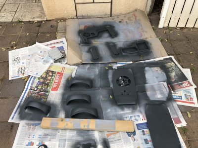
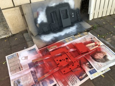
I decided to go with a black and white color theme with touches of red. Also, this mod would have some Star Wars/Stormtrooper/Galactic Empire vibes.
- sorry for bad English cause its not my native language.
- Specs:
i5 3550
GTX 55ti
1TB HDD
12GB RAM
*This is not going to be my main system. I'm doing this for the case mod and ill put my old pc parts in there, so the case would be completely standard and upgradable.
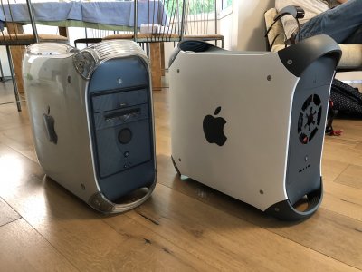
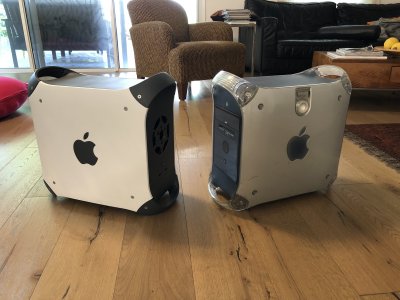
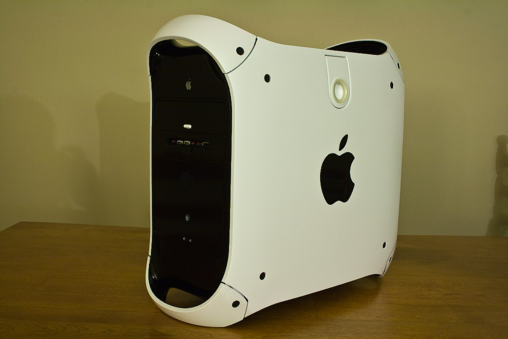
This is what I started with - 1st gen power mac g4:
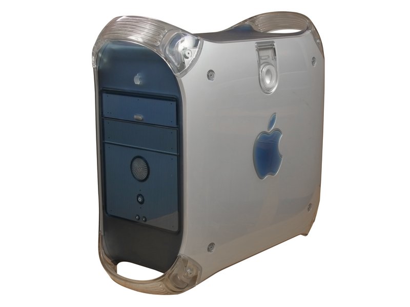
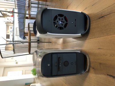
In the end I want it to look something like this but with some personal touches:
So.. I completely tore down the case.
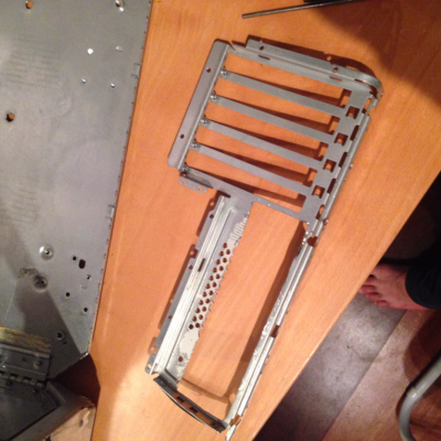
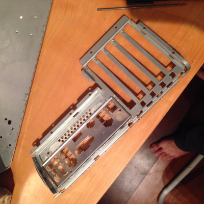
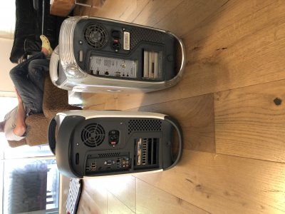
The first thing I had to do is to mod the rear panel to fit a standard I/O shield. I cut out rectangle-ish piece:


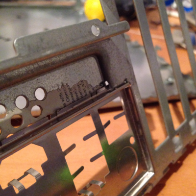
In the last photo, you can see that the IO shield sits really nicely and flat with the back panel, to do so, I cut a tiny slot in the gap between the lower and higher parts:

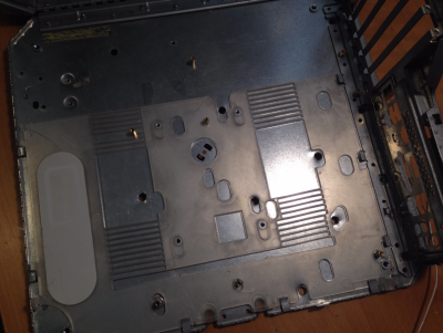
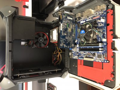
The next step was to mount the motherboard standoffs. To do so, I put the mobo in its place with a GPU and I screwed in the gpu to the chassis so it would be fitted perfectly. Then I used a drill and Dremel to make oval slots in the plastic plate for the standoffs (so the door will be able to open).


I decided to keep the PSU in its original place, with the fan to the outside of the case so I drilled big holes in back for airflow,
it's not the best solution but it won't be visible so I don't really care. I also removed the shelf for the PSU and optical drive.

For the front panel I wanted to do something that would look cool so cut out the middle section with a Dremel. I designed a front panel using Solidworks and then I laser cut it from 3mm acrylic.


I gave up on the two buttons under the power button, and instead, I used the space for the front I/O (2XUSB 3.0, headphones and microphone jacks). For power button, I'm using the original one.
I also designed a back panel for the front panel to mount the fan on it, a PSU cover with the empire logo, and a mount for the front I/O:


This is where I am now, more updates will be posted as soon as possible!
Feel free to ask questions and suggest things!
My parents are working with Macs for a long time now and I have 3 old Power Macs G4. For this summer, i wanted a project to work on so I decided to mod one of the G4s just for fun.
In this thread, I will update my experience and progress for this awesome mod.
I decided to go with a black and white color theme with touches of red. Also, this mod would have some Star Wars/Stormtrooper/Galactic Empire vibes.
- sorry for bad English cause its not my native language.
- Specs:
i5 3550
GTX 55ti
1TB HDD
12GB RAM
*This is not going to be my main system. I'm doing this for the case mod and ill put my old pc parts in there, so the case would be completely standard and upgradable.
This is what I started with - 1st gen power mac g4:
In the end I want it to look something like this but with some personal touches:
So.. I completely tore down the case.
The first thing I had to do is to mod the rear panel to fit a standard I/O shield. I cut out rectangle-ish piece:
In the last photo, you can see that the IO shield sits really nicely and flat with the back panel, to do so, I cut a tiny slot in the gap between the lower and higher parts:
The next step was to mount the motherboard standoffs. To do so, I put the mobo in its place with a GPU and I screwed in the gpu to the chassis so it would be fitted perfectly. Then I used a drill and Dremel to make oval slots in the plastic plate for the standoffs (so the door will be able to open).
I decided to keep the PSU in its original place, with the fan to the outside of the case so I drilled big holes in back for airflow,
it's not the best solution but it won't be visible so I don't really care. I also removed the shelf for the PSU and optical drive.
For the front panel I wanted to do something that would look cool so cut out the middle section with a Dremel. I designed a front panel using Solidworks and then I laser cut it from 3mm acrylic.
I gave up on the two buttons under the power button, and instead, I used the space for the front I/O (2XUSB 3.0, headphones and microphone jacks). For power button, I'm using the original one.
I also designed a back panel for the front panel to mount the fan on it, a PSU cover with the empire logo, and a mount for the front I/O:
This is where I am now, more updates will be posted as soon as possible!
Feel free to ask questions and suggest things!